192277 - Micron Technical Reference V9 Volume 1.pdf - 第289页
PROFLOW MODULE ADJUSTMENTS AND SETTINGS Chapter Issue 16, Nov 18 T echnical Reference Manual 11.7 Height Adjustment T o set the ProFlow stencil support to the correct height carry out the following: 1. Loosen the 7mm hex…

PROFLOW MODULE
ADJUSTMENTS AND SETTINGS
11.6 Technical Reference Manual Chapter Issue 16, Nov 18
ADJUSTMENTS AND SETTINGS
ProFlow Paste
Level Sensor
There is no adjustment and setting for this sensor.
ProFlow Stencil
Support
The ProFlow stencil support option provides stencil support when printing
boards that are narrower than the ProFlow transfer head, thus avoiding poten-
tial paste smearing onto the top of the stencil and stabilising the pressure within
the transfer head.
The standard height when the adjustable tooling top is in the closed position is
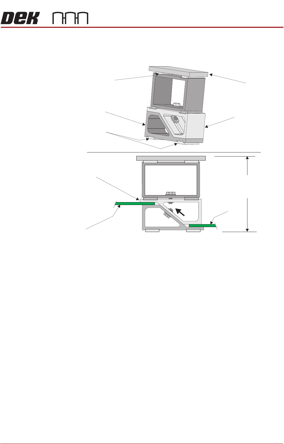
81mm. The support comprises the following items:
• Changeable Gauge Plate
• Tooling Bottom
• Adjustable Tooling Top
NOTE
Refer to Board Support Tooling chapter of this manual for further information.
PROFLOW MODULE
ADJUSTMENTS AND SETTINGS
Chapter Issue 16, Nov 18 Technical Reference Manual 11.7
Height Adjustment To set the ProFlow stencil support to the correct height carry out the following:
1. Loosen the 7mm hexagonal nut securing the adjustable tooling top and the
tooling bottom.
2. Slide the adjustable tooling top upwards to open up the tooling top and
bottom faces.
3. Position two printed circuit boards to be printed between the adjustable
tooling top and tooling bottom opening faces.
4. Tighten the bolt locking the adjustable tooling top to the tooling bottom.
5. Remove both printed circuit boards.
The support is now set to the correct stencil height, ie 81mm + thickness of
board.
Changeable
Gauge Plate
Too ling Bottom
Magnetic Feet
Magnetic Support
(2 positions)
AdjustableTooling
Top
Board
Adjustable
Too ling Top
Board
Stencil Support
Height (81mm +
PCB Thickness)
PROFLOW MODULE
REPLACEMENT PROCEDURES
11.8 Technical Reference Manual Chapter Issue 16, Nov 18
REPLACEMENT PROCEDURES
Squeegees to
ProFlow
Instances may occur when the machine is required to print using the ProFlow
module configuration. The following procedure details how to revert the
machine from squeegee use to the ProFlow configuration:
Removing
Squeegee
Mechanism
1. Select Open Cover Commands.
2. If required, select Carriage To Front.
3. Select Back.
4. Select Shut Down.
5. Select Continue.
6. Switch the mains isolator to OFF; lockout the mains isolator.
7. Remove the squeegees, if fitted.
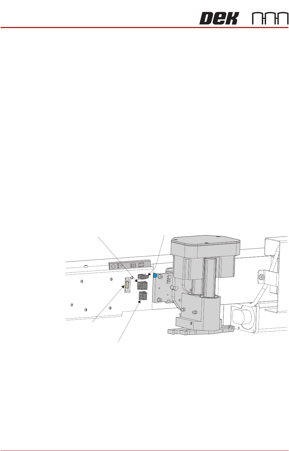
8. Disconnect the four squeegee mechanism connectors from the print car-
riage, left hand side:
• Rear Squeegee Motor
• Front Squeegee Motor
• Home Sensors
• Squeegee Pressure Amplifier
9. Loosen the four captive screws securing the squeegee printhead mecha-
nism to the print carriage using a 4mm Allen key. Carefully remove the
mechanism from the print carriage.
Rear Squeegee
Motor (9SK17)
Front Squeegee
Motor (9SK16)
Home Sensors
(9SK08)
Squeegee Pressure
Amplifier (N3SK16)