192277 - Micron Technical Reference V9 Volume 1.pdf - 第241页
SQUEEGEE MODULE REPLACEMENT PROCEDURES Chapter Issue 8, May 19 Technical Reference Manual 9.9 Fitting Drip T ray 1. Slide the slot in the drip tray onto the bea ring on the drip tray guide shaft. 2. Secure the drip tray …
SQUEEGEE MODULE
REPLACEMENT PROCEDURES
9.8 Technical Reference Manual Chapter Issue 8, May 19
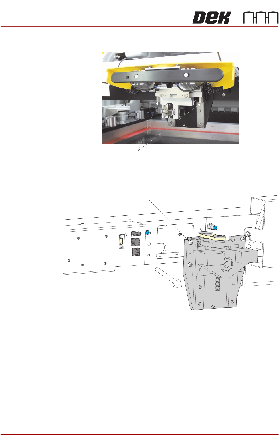
19. Release the pressure mechanism from the printhead mechanism by
unscrewing the two securing bolts, using a 5mm Allen key.
20. Loosen the four captive screws securing the ProFlow printhead mechanism
to the print carriage using a 4mm Allen key. Carefully remove the mecha-
nism from the print carriage.
Securing Bolts
Captive Screw (in 4 positions)
SQUEEGEE MODULE
REPLACEMENT PROCEDURES
Chapter Issue 8, May 19 Technical Reference Manual 9.9
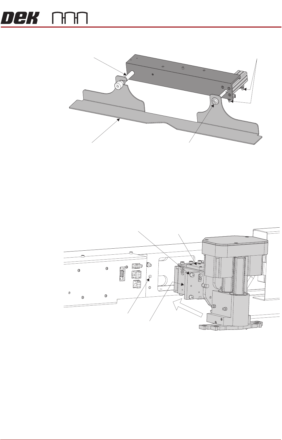
Fitting Drip Tray 1. Slide the slot in the drip tray onto the bearing on the drip tray guide shaft.
2. Secure the drip tray to the actuator piston using the securing screw.
3. Open the speed control valves on the drip tray actuator.
Fitting Squeegee 1. Carefully position the rear of the printhead mechanism (spring beam
assembly) into the print carriage so that both printhead mechanism dowels
locate into the print carriage locating holes. Secure the unit to the print
carriage by means of the four captive screws, ensuring the pneumatic pipe
is not trapped.
Drip Tray
Drip Tray Guide Shaft
Securing Screw
Speed Control Valves
Captive Screw (in 4 positions) Spring Beam Assembly
Locating Dowel
(in 2 positions)
Print Carriage Locating
Hole (in 2 positions)
SQUEEGEE MODULE
REPLACEMENT PROCEDURES
9.10 Technical Reference Manual Chapter Issue 8, May 19
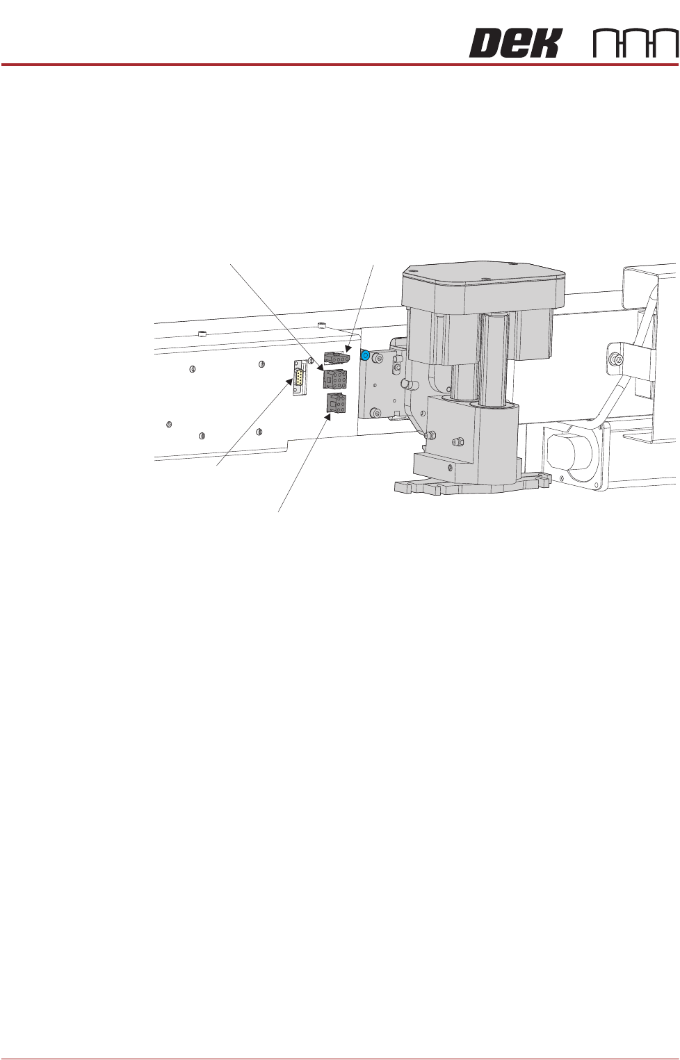
2. Connect the following connectors to the print carriage, left hand side:
• Rear Squeegee Motor
• Front Squeegee Motor
• Home Sensors
• Squeegee Pressure Amplifier
3. Fit the required configuration of squeegees to the printhead mechanism
squeegee mounts.
NOTE
Squeegee fitting information is detailed in the Replacement Procedures
section of this chapter.
4. Close the printhead cover.
5. Remove the isolator lock; turn the mains isolator ON and ensure that the
machine recognizes the squeegee module fit by displaying Squeegees
Uninitialised during the machine initialisation sequence.
6. Press the System button.
Drive Belt
Replacement
1. Select Open Cover Commands.
2. Select Carriage To Front.
3. Select Back.
4. Select Shut Down.
5. Select Continue.
6. Switch the mains isolator to OFF; lockout the isolator.
7. Open the printhead cover.
8. Remove the squeegees, if fitted.
9. Remove the drive belt cover plate from the squeegee printhead mechanism
Rear Squeegee
Motor (9SK17)
Front Squeegee
Motor (9SK16)
Home Sensors
(9SK08)
Squeegee Pressure
Amplifier (N3SK16)