192277 - Micron Technical Reference V9 Volume 1.pdf - 第269页
PROACTIV ADJUSTMENTS AND SETTINGS Chapter Issue 6, Nov 18 Techn ical Reference Manual 10.13 17. Ensure that the calibration jig is secured to the mounting p late as shown in the following graphic: Mounting P l ate Mounti…

PROACTIV
ADJUSTMENTS AND SETTINGS
10.12 Technical Reference Manual Chapter Issue 6, Nov 18
NOTE
Ensure that the rising table print reference height is set correctly before com-
mencing, (the calibration relies upon accurate positioning of the table to make
a reference).
WARNING
BOARD CLAMPS. EXTREME CARE MUST BE EXERCISED WHEN WORKING IN
THE TOOLING AREA OF THE MACHINE TO AVOID INJURY. THE FOILS ON THE
FRONT AND REAR BOARD CLAMPS ARE VERY SHARP.
1. Select Open Cover Commands.
2. If required, select Carriage To Rear.
3. Select Unload Screen.
4. Open the printhead cover.
5. Remove the screen from the printer.
6. Remove the tooling from the tooling plate.
7. Close the printhead cover.
8. Press the System button.
9. Select Back.
10. Select Maintenance.
11. Select Calibrations.
12. Select Classic Calibrations.
13. Select Pressure.
14. Select Calibrat Readings. The rails are checked for the presence of a
board, the print carriage moves to the calibration position, the rear rail
moves to home position, the table homes and the board clamps are closed.
15. The machine cover is unlocked and the message ‘Calibrating Reading -
Fit pressure calibration rig.’ is displayed with the following window:
16. Open the printhead cover.
CALIBRATION DATA
Gain Factor
1.02
PROACTIV
ADJUSTMENTS AND SETTINGS
Chapter Issue 6, Nov 18 Technical Reference Manual 10.13
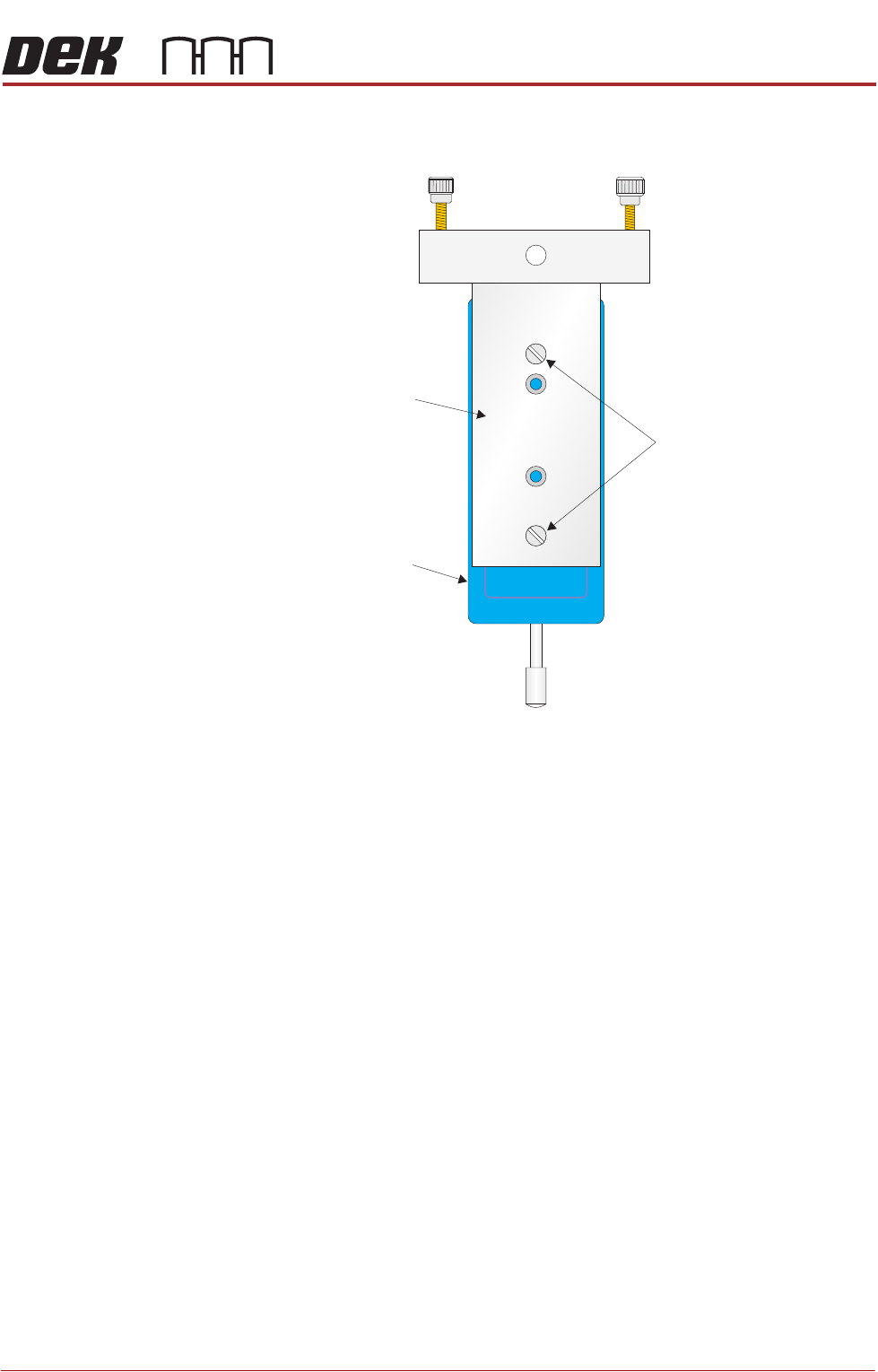
17. Ensure that the calibration jig is secured to the mounting plate as shown in
the following graphic:
Mounting Plate
Mounting Holes
Calibration Jig
A
A
S
S
PROACTIV
ADJUSTMENTS AND SETTINGS
10.14 Technical Reference Manual Chapter Issue 6, Nov 18
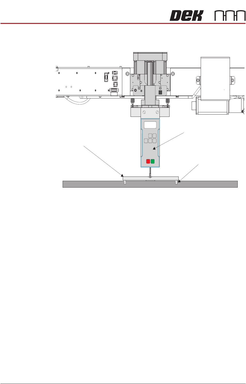
18. Fit the calibration jig to the front squeegee position using the outer mounting
holes on the front foot assembly.
19. Fit the squeegee pressure plate to the rising table ensuring that the locating
dowels insert into the holes of the rising table.
NOTE
During the squeegee pressure calibration the dwell height of the rear
squeegee is 15mm regardless of the set up value. This height is set during
calibration only.
20. Switch the force meter ON and check the reading is 0kg, (ensure the force
meter is not in contact with the squeegee pressure plate).
21. Close the printhead cover.
22. Press the System button.
23. Select Continue.
View on Front ofR ising Table and S queegee M echanism
Squeegee Pressure Plate
Locating Dowel
(in 2 positions)
O
OFF
I
ON
UNITS
Zero
MAX TXD
RESET
00.00
Portable Force Gauge
(Calibration Jig)