西门子SIPLACE HF-设备参数_US.pdf - 第13页
13 Placement Heads TwinHead for High-Pre cision IC Placement Innovation • Th e Tw in Head pl aces two compon ents at the same time using the Pic k & Place metho ds → Increase d speed w hen placing larg e components →…
12
Placement Heads
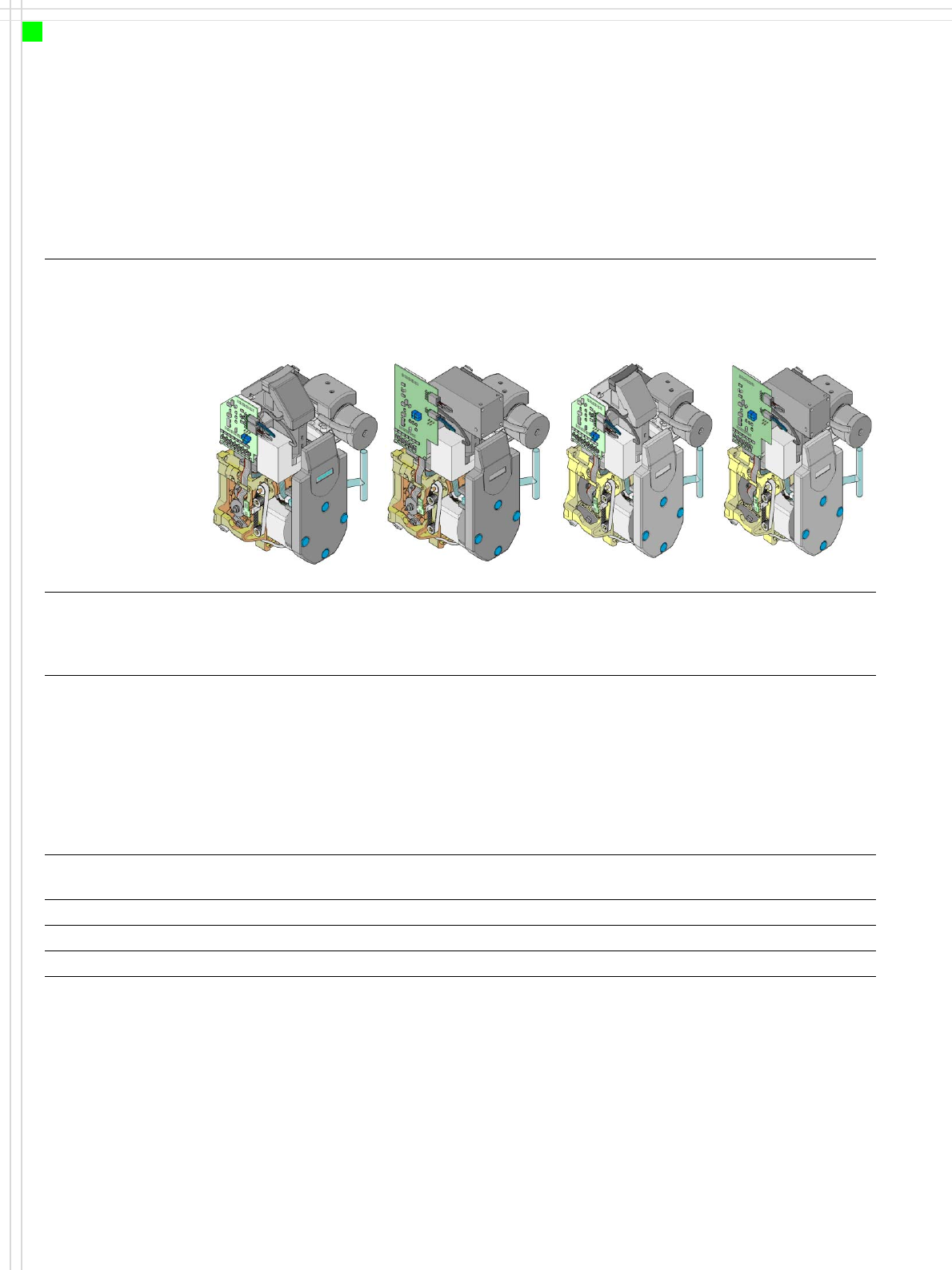
Collect & Place Heads
Technical Data
Please note that the component range that can be placed is also affected by the pad geometry,
the customer-specific standards and the component packaging tolerances.
12-segment
Collect & Place head
(standard
vision module)
12-segment
Collect & Place head
(DCA vision module
)
6-segment
Collect & Place head
(standard
vision module
)
6-segment
Collect & Place head
(DCA vision module
)
Component range 0201 to PLCC44,
BGA, µBGA, flip-chip,
TSOP, QFP, SO to
SO32, DRAM
0201 to flip-chip, bare
die
0603 to 32 x 32 mm² 0201 to flip-chip,
bare die
Component
specifications
max. height
min. lead pitch
min. bump pitch
min. ball bump ∅
min. dimensions
max. dimensions
max. weight
6 mm
0.5 mm
0.35 mm
0.2 mm
0.6 x 0.3 mm²
18.7 x 18.7 mm²
2 g
6 mm
0.4 mm
0.2 mm
0.11 mm
0.6 x 0.3 mm²
13 x 13 mm²
2 g
8.5 mm
0.5 mm
0.56 mm
0.32 mm
1.6 x 0.8 mm²
32 x 32 mm²
5 g
8.5 mm
0.4 mm
0.2 mm
0.11 mm
0.6 x 0.3 mm²
13 x 13 mm²
5 g
Programmable
set-down force 2.4 N - 5.0 N 2.4 N - 5.0 N 2.4 N - 5.0 N 2.4 N - 5.0 N
Nozzle types 9 xx 9 xx 8 xx, 9 xx 8 xx, 9 xx
X/Y accuracy ± 60 µm/4 σ ± 55 µm/4 σ ± 60 µm/4 σ ± 55 µm/4 σ
Angular accuracy ± 0.7°/4 σ ± 0.7°/4 σ ± 0.3°/4 σ ± 0.3°/4 σ
13
Placement Heads
TwinHead for High-Precision IC Placement
Innovation
• The TwinHead places two
components at the same
time using the Pick & Place
methods
→ Increased speed when
placing large components
→ Greater flexibility due to
broader range of compo-
nents
Description
This sophisticated placement
head consists of two place-
ment heads of the same type
coupled together (twin
head). Both heads work
using the Pick & Place prin-
ciple. The TwinHead is suit-
able for processing partic-
ularly difficult or large com-
ponents. Two components
are picked up by the place-
ment head, optically cen-
tered on the way to the
placement position and
rotated into the necessary
placement angle. The com-
ponents are then placed
gently and accurately on the
board.
In addition to the vacuum
nozzles specially developed
for the TwinHead, the place-
ment head can also use the
nozzles for the Pick & Place
head. Collect &Place head
nozzles can also be used.
Checking and self-learning
functions
The TwinHead's reliability
can be further increased with
various checking and self-
learning functions.
• For example, vacuum
checks at the nozzles indi-
cate whether the compo-
nent was picked up or set
down correctly.
• High-resolution, intelli-
gent vision modules, such
as the fine-pitch and flip-
chip vision modules, iden-
tify and correct minute
deviations from the
desired component posi-
tion, thus guaranteeing a
correct placement posi-
tion. The vision modules
are permanently fixed to
the machine frame.
• The component package
form is also checked, and
the component is not
placed if the geometric
data thus determined dif-
fers from the programmed
data.
• A force sensor measures
and monitors the specified
component placement
forces.
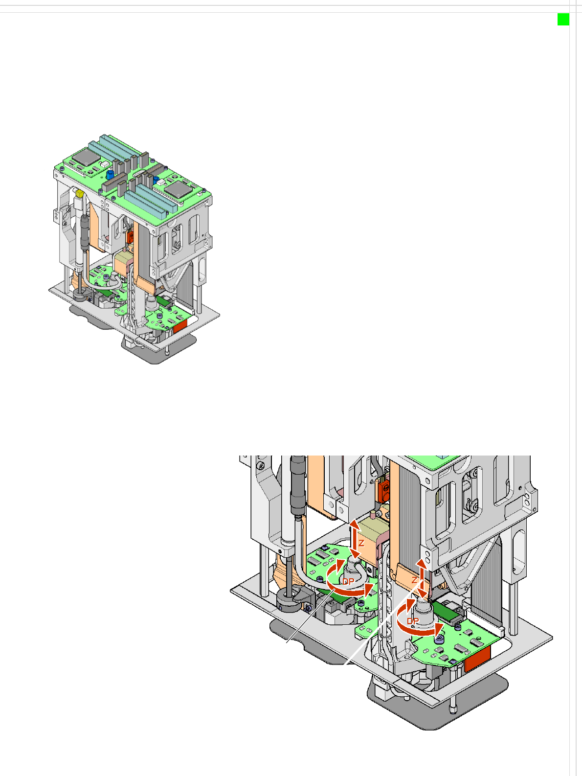
Z axis
DP axis
How the TwinHead works
14
Placement Heads
TwinHead for High-Precision IC Placement
Technical Data
*) Please note that the component range that can be placed is also affected by the pad geometry,
the customer-specific standards and the component packaging tolerances.
**) When using the multi-color camera, the height reduces to 18.3 mm.
***) If standard nozzles are used
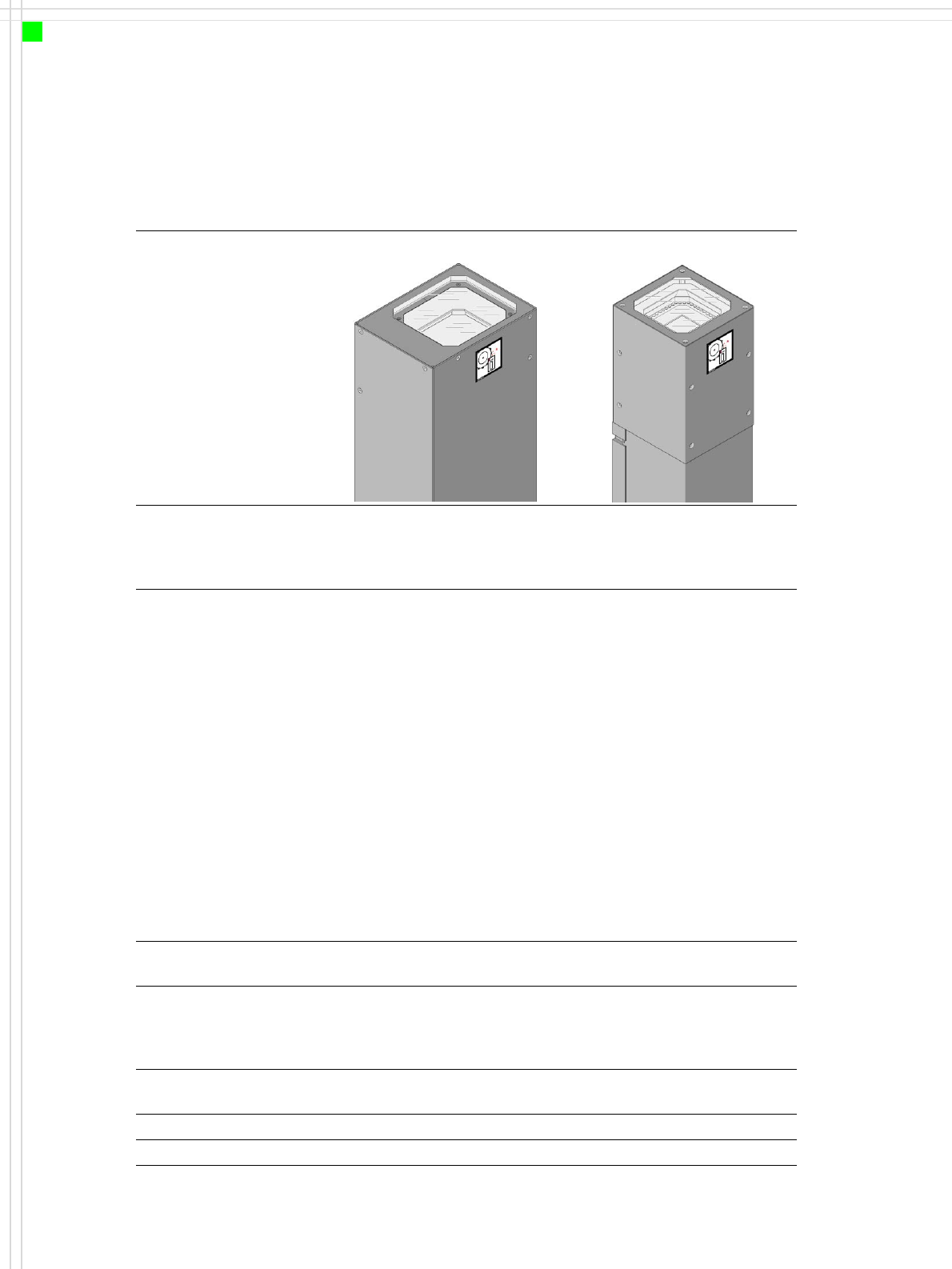
Optical centering with Fine-pitch vision module Flip-chip vision module
Component range
*)
0603 to SO, PLCC, QFP, BGA,
special components, bare dies,
flip-chips
0201 to SO, PLCC, QFP, sock-
ets, plugs, BGA, special com-
ponents, bare dies, flip-chips,
shields
Component
specifications
max. height
min. lead pitch
min. bump pitch
min. ball ∅
min. dimensions
max. dimensions
max. weight
25 mm
**)
0.4 mm
0.56 mm
0.32 mm
1.6 x 0.8 mm²
50 x 40 mm²
(single measurement)
For use with two nozzles
50 x 50 mm² or
69 x 10 mm²
For use with one nozzle:
85 x 85 mm² or
125 x 10 mm²
max. 200 x 125 mm² (with
restrictions)
100 g
***)
25 mm
**)
0.25 mm
0.14 mm
0.08 mm
0.6 x 0.3 mm²
8 x 8 mm²
(single measurement)
100 g
***)
Programmable place-
ment force
1.0 N - 15 N 1.0 N - 15 N
Nozzle types 5 xx (standard)
4 xx + adapter
8 xx + adapter
9 xx + adapter
5 xx (standard)
4 xx + adapter
8 xx + adapter
9 xx + adapter
Nozzle spacing on the
two Pick & Place heads
70.8 mm 70.8 mm
X/Y accuracy ± 35 µm/4 σ ± 30 µm/4 σ
Angular accuracy 0.07° / 4 σ 0.07° / 4 σ