西门子SIPLACE HF-设备参数_US.pdf - 第19页
19 PCB Conveyor Single Conve yor Technical Data *) With PCB widths > 45 0 mm make sure that the periphe ral module s are also able to pr ocess these widths. Fixed c onvey or side Right or left PCB format Standard (len…
18
Placement area 1
Placement area 2
Output conveyor
Intermediate conveyor
Input conveyor
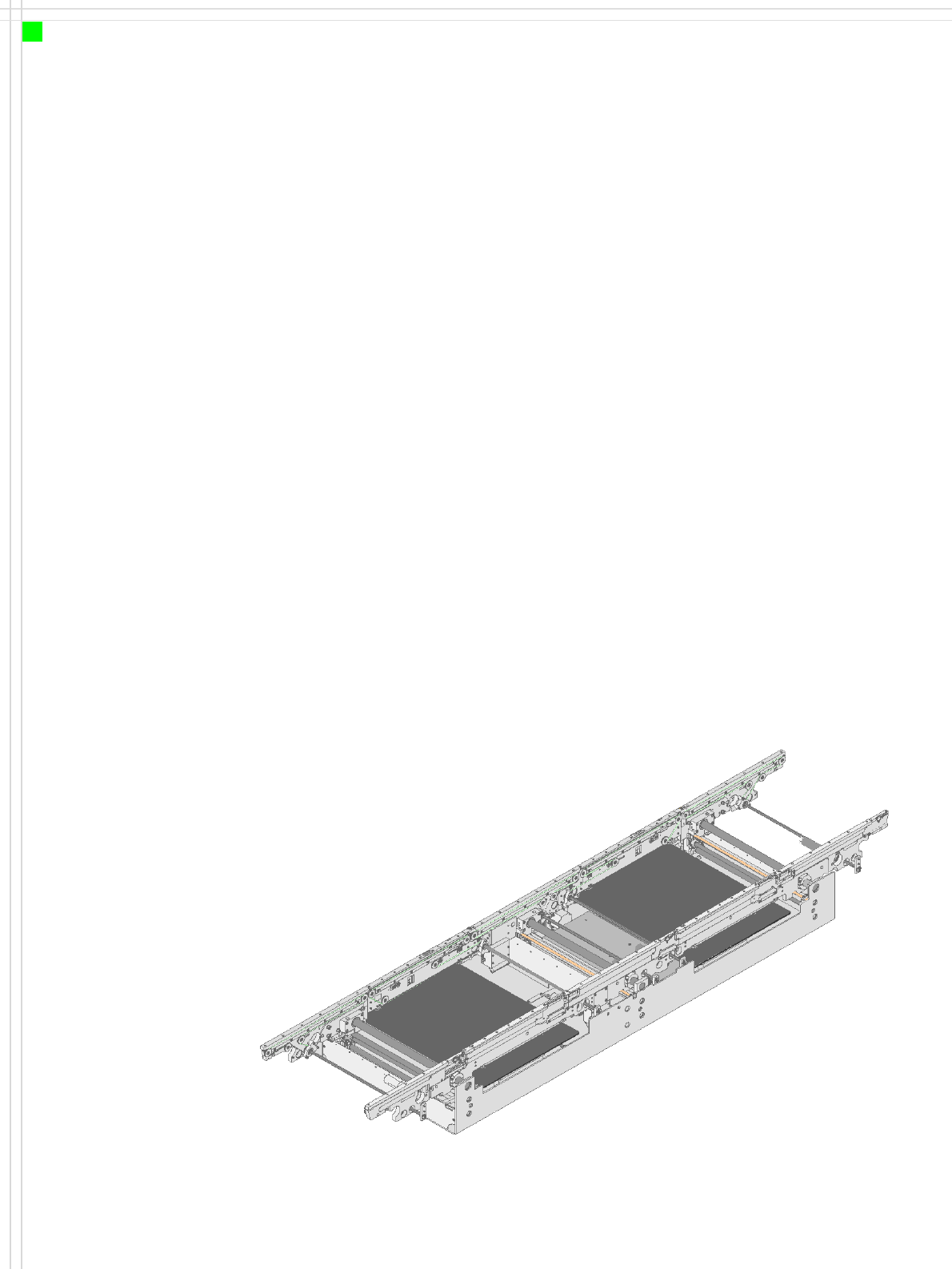
PCB Conveyor
Single Conveyor
Innovation
• The PCB is clamped from
below for placement
→ distance between the
PCB and placement head is
always constant
→ placement rate does
not depend on the PCB
thickness
→ fiducial contours are
always sharply displayed
→ improved PCB fiducial
centering
• The width adjustment unit
has a dedicated control
circuit
→ independent of other
machine components
→ faster and easier to
adjust
Description
For placement, the PCB is
clamped from below. The dis-
tance between the top of the
PCB and the placement head
thus remains unchanged for
each PCB, and is no longer
dependent on the thickness
of the PCB. The placement
rate is thus also independent
of the PCB thickness.
Since the distance between
the PCB surface and the PCB
camera remains the same,
the PCB camera is always
focussed on the PCB surface
with the same level of sharp-
ness.
The PCB fiducial contours
are optimally mapped on the
CCD chip of the PCB camera.
The inline PCB conveyor sys-
tem quickly adapts to a wide
range of PCB widths. The set-
ting is made using the place-
ment program or via the
station software menu. The
width of the PCB conveyor is
monitored by an integral
control circuit.
The transport height can be
modified, thus allowing the
machines to be integrated
into lines with a transport
height of 830, 900, 930 or
950 mm.
The PCB conveyors can com-
municate with the individual
machines via the SMEMA
interface.
The fixed transport side can
be located on the left or right
for both the dual conveyor
and the single conveyor.
With this conveyor, the fixed
side can be easily switched
from right to left or vice
versa.
Movement and clamping of
the PCBs are monitored and
controlled by sensors. When
the board has reached the
placement area and passed
the light barrier, it is braked.
A laser light barrier deter-
mines the position of the
board. As soon as the circuit
board has reached its target
position, the conveyor belt is
stopped and the board is
clamped from the underside.
The placement process then
starts immediately.

19
PCB Conveyor
Single Conveyor
Technical Data
*) With PCB widths > 450 mm make sure that the peripheral modules are also able to process these widths.
Fixed conveyor side Right or left
PCB format
Standard (length x width)
"Wide board" configuration
"Long board" option
"Long board" option in "Wide board" configuration
50 x 50 mm² to 450 x 450 mm²
50 x 50 mm² to 450 x 508 mm²
*)
50 x 80 mm² to 610 x 450 mm²
50 x 80 mm² to 610 x 508 mm²
*)
PCB thickness
Standard 0.3 mm to 4.5 mm (± 0,2 mm)
(thicker PCBs on request)
Max. PCB warpage Up: 6 mm - PCB thickness
Down: 0.3 mm + PCB thickness
PCB weight max. 3 kg
Clearance on PCB underside
Standard
Option
25 mm ± 0.2 mm
max. 40 mm ± 0.2 mm
Component-free PCB handling edge 3 mm
PCB changeover time < 2.5 s
PCB positioning accuracy ± 0.5 mm
PCB transport height 830mm ± 15mm (standard)
900mm ± 15mm (SMEMA)
930mm ± 15mm (SMEMAl)
950mm ± 15mm (SMEMA)
Type of interface SMEMA / SIEMENS
Ink spot detection possible
Automatic width adjustment possible
20
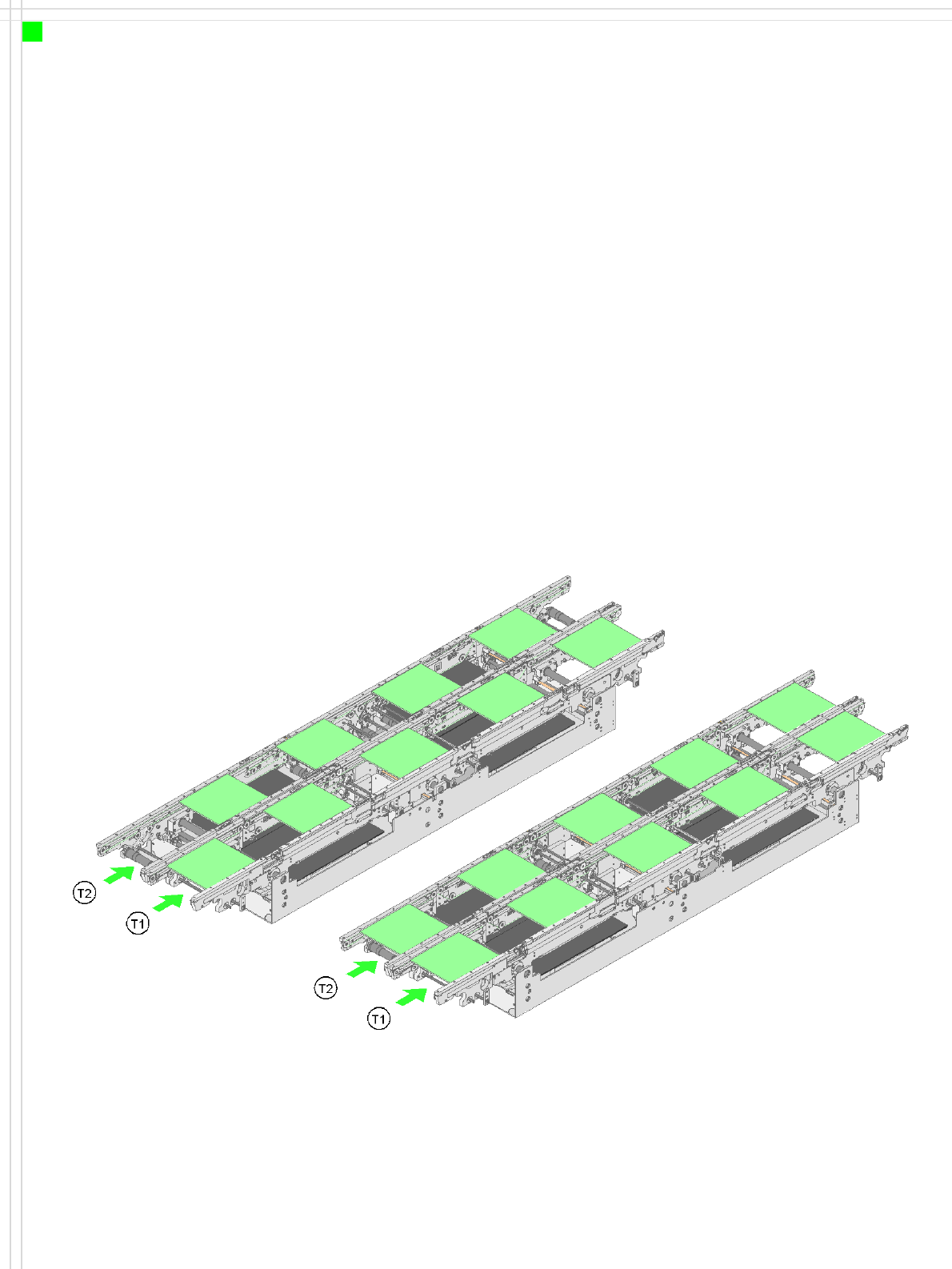
Asynchronous conveyor mode
Synchronous conveyor mode
PCB Conveyor
Flexible Dual Conveyor
Innovation
•As for single conveyor
Plus:
• The dual conveyor can be
configured online to
create a single conveyor →
no mechanical conversion
work required
• Reduced down times →
increased production
throughput
Description
The PCB dual conveyor can
greatly increase throughput
with shorter down times -
depending on the placement
program. It allows two PCBs
to be carried simultaneously
(synchronously) or alternate-
ly (asynchronously) through
the placement machine.
In asynchronous mode, only
one PCB in a transport track is
processed. At the same time,
another PCB in the second
transport track is moved into
the placement position. This
saves the full conveying time
of one PCB, thus considerably
increasing performance, par-
ticularly for PCBs with a short
cycle time. The placement
process starts as soon as one
PCB is transported into the
processing area.
In synchronous mode, two
PCBs are moved into the
placement position at the
same time. They are pro-
cessed as a common panel.
In this way, the top and bot-
tom of a PCB can be pro-
cessed on a single line, The
proportion of non-productive
time is reduced as two circuit
boards are always conveyed
simultaneously.