西门子SIPLACE HF-设备参数_US.pdf - 第7页
7 Machine Description Technical Data T ypes of placeme nt head SIPL ACE T winHead (TH) 6-seg ment Col lect & Place h ead (C&P6) 12-segmen t Collec t & Place h ead (C &P12) Numb er of gantri es 2 Placemen …
6
Machine Description
Overview
Upgrade
The following options are
available to extend the
machine's functionality:
• Additional component
changeover tables
increase machine utiliza-
tion since set-up times can
be reduced by carrying out
preliminary set-up off the
machine.
•The dual conveyor also
increases machine utiliza-
tion by eliminating non-
productive PCB transport
times.
• Automatic nozzle chang-
ers speed up and optimize
the nozzle configuration
process.
• PCB barcode scanners
allow the production set-
up to be changed over
when triggered by a new
product.
• Component barcode scan-
ners optimize the set-up
and refill checks.
• Large and sensitive fine-
pitch components can be
supplied in trays by two
matrix tray changers.
• The productivity lift imple-
ments the concept of par-
allel placement, and thus
improves the ratio be-
tween productive and
non-productive times.
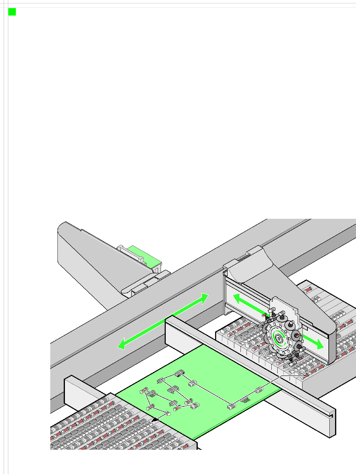
Placement principle
Collect & Place

7
Machine Description
Technical Data
Types of placement head SIPLACE TwinHead (TH)
6-segment Collect & Place head (C&P6)
12-segment Collect & Place head (C&P12)
Number of gantries 2
Placement rate
(benchmark)
Placement area 1 Placement area 2
C&P12 C&P12 28,000 comp./h
C&P12 C&P6 23,300 comp./h
C&P6 C&P6 18,600 comp./h
C&P12 TH 17,700 comp./h
C&P6 TH 13,000 comp./h
TH TH 7,400 comp./h
Range of components 0.6 x 0.3 mm² (0201) to 85 x 85 mm² / 125 x 10 mm²
max. 200 x 125 mm² (with restrictions)
Component height C&P12: 6 mm
C&P6: 8.5 mm
TH: 25 mm (When using the multi-color camera, the height
reduces to 18.3 mm.)
Placement accuracy C&P12: ± 60 µm standard, ± 55 µm DCA, ± 0.7° / (4 σ)
C&P6: ± 60 µm standard, ± 55 µm DCA, ± 0.3° / (4 σ)
TH: ± 35 µm standard, ± 30 µm FC, ± 0.07° / (4 σ)
PCB format
(LxW)
PLEASE NOTE:
With PCB widths > 450 mm
make sure that the peripheral
modules are also able to pro-
cess these widths.
Single conveyor
50 x 50 mm² to 450 x 508 mm²
50 x 80 mm² to 610 x 508 mm² ("Long board" option)
Dual conveyor
50 x 50 mm² to 450 x 250 mm²
50 x 80 mm² to 610 x 250 mm² ("Long board" option)
Dual conveyor in Single conveyor mode
50 x 50 mm² to 450 x 450 mm²
50 x 80 mm² to 610 x 450 mm² ("Long board" option)
PCB thickness 0.3 - 4.5 mm (thicker PCBs on request)
Feeding capacity 180 tracks, width 8 mm (60 3 x 8 mm S feeder)
120 tracks, width 8 mm (60 2 x 8 mm S feeder)
60 tracks, width 12 or 16 mm (60 12/16 mm S feeder)
40 tracks, width 24 or 32 mm (40 24/32 mm S feeder)
28 tracks, width 44 mm (28 44 mm S feeder)
24 tracks, width 56 mm (24 56 mm S feeder)
20 tracks, width 72 mm (20 72 mm S feeder)
16 tracks, width 88 mm (16 88 mm S feeder)
Component feeding 4 component changeover tables with tape roll holders and integral
waste containers, 15 slots, 30 mm wide, per changeover table or
up to 2
matrix tray changers, rather than component changeover
tables
Feeder module types Tapes, bulk cases, stick magazines, application-specific OEM
feeders, surftape feeders (8, 12, 16 mm), manual trays
Electrical ratings and com-
pressed air specification
see page 32
Dimensions and set-up condi-
tions
see page 34
8
Line Concept
Description
Innovation
• Modularity, flexibility
→ the line can easily be
adapted to suit production
requirements
• Compactness, high power
density → less space
required for increased
placement rate
Description
The SIPLACE HF is fully com-
patible with other SIPLACE
systems. This compatibility
enables a production line to
be configured from identical
and different modules. If pro-
duction requirements
change, the individual place-
ment systems can be quickly
and easily recombined.
The SIPLACE family has exact-
ly the right placement sys-
tem, whatever the output
requirements:
SIPLACE HF placement sys-
tems place the entire SMD
spectrum of components
from 0201 to 125 x 10 mm²
with a high placement rate.
The SIPLACE HS-60 is a super
high-speed placement sys-
tem for processing compo-
nents ranging from 0201
through to 18.7 x 18.7 mm².
The SIPLACE S-27 HM is a
high-speed system for plac-
ing components from 0201
to 32 x 32 mm².
The flexible SIPLACE F5 HM
system places large ICs, flip
chips, bare dies and exotic
components (OSC). It has a
component range of 0201 to
55 x 55 mm².
SIPLACE set-up optimization
is a tool for increasing the
line's productivity.
The software calculates indi-
vidual set-ups for individual
products, individual set-ups
f o r d i f f e r e n t p r o d u c t s a n d
family set-ups for different
products.
The program data can be ex-
changed between the indi-
vidual lines - even for
different machine
configurations.
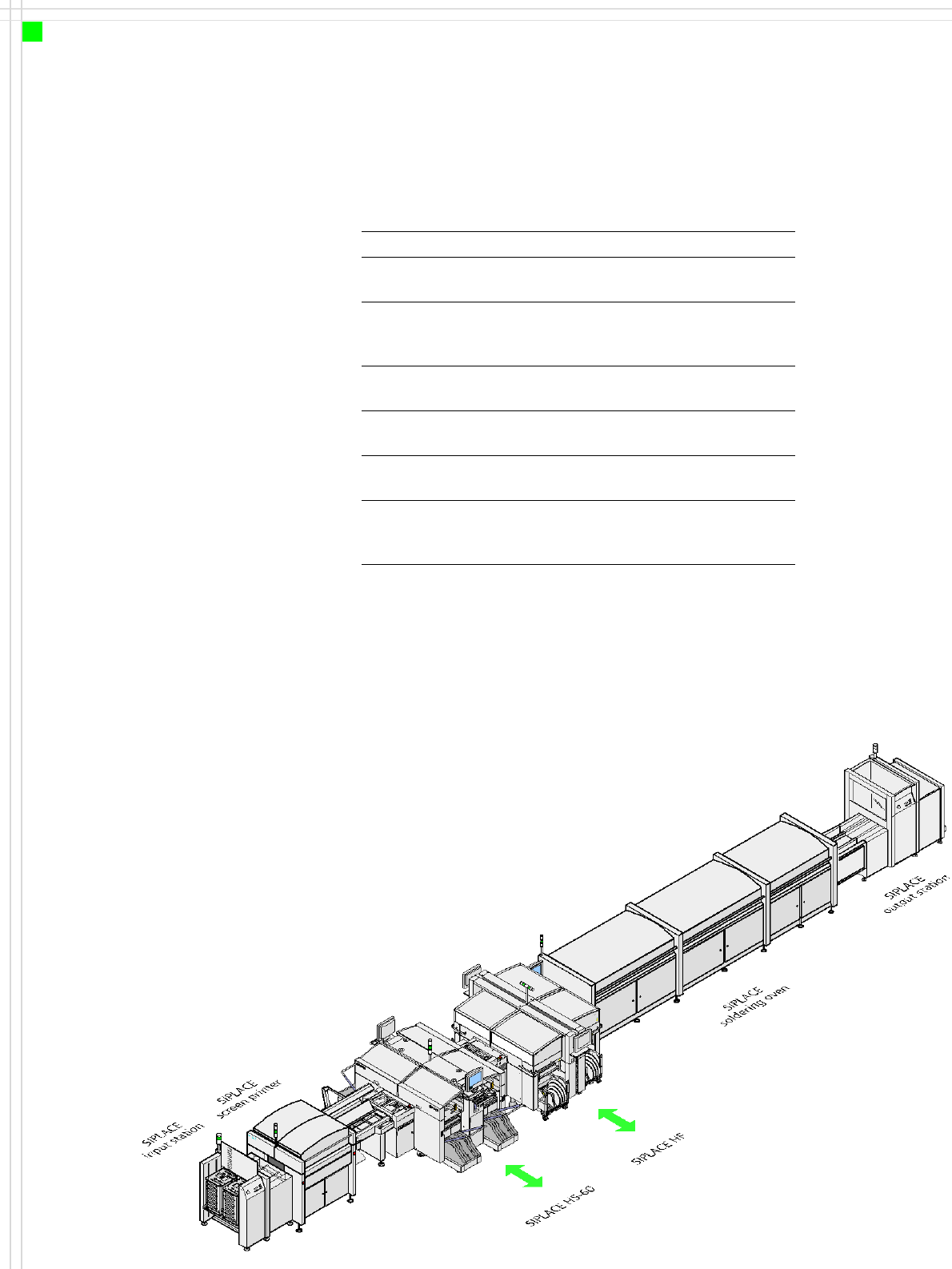
System SIPLACE SMD placement lines
Placement
modules
SIPLACE HF / SIPLACE HS-60 / SIPLACE
S-27 HM / F5 HM
Peripheral
modules
Input/output stations, screen printers,
soldering ovens, inspection stations, etc,
available from SIEMENS A&D EA
Component
range
0201 to 85 x 85 mm² / 125 x 10 mm²
max. 200 x 125 ² mm² (with restrictions)
PCB conveyor Single and dual conveyor with automatic
width adjustment unit
Placement
rate
Depends how modules are connected in
series
Space
required
4 m² per S module,
6.7 m² per HF and HF/3 module,
7.5 m² per HS module