西门子SIPLACE HF-设备参数_US.pdf - 第8页
8 Line Concept Description Innovation • Modularity, flexi bility → the line c an easily be adapt ed to sui t pro duc tion requirem ents • Compactness, high power densit y → less space required f or incr eased placem ent …

7
Machine Description
Technical Data
Types of placement head SIPLACE TwinHead (TH)
6-segment Collect & Place head (C&P6)
12-segment Collect & Place head (C&P12)
Number of gantries 2
Placement rate
(benchmark)
Placement area 1 Placement area 2
C&P12 C&P12 28,000 comp./h
C&P12 C&P6 23,300 comp./h
C&P6 C&P6 18,600 comp./h
C&P12 TH 17,700 comp./h
C&P6 TH 13,000 comp./h
TH TH 7,400 comp./h
Range of components 0.6 x 0.3 mm² (0201) to 85 x 85 mm² / 125 x 10 mm²
max. 200 x 125 mm² (with restrictions)
Component height C&P12: 6 mm
C&P6: 8.5 mm
TH: 25 mm (When using the multi-color camera, the height
reduces to 18.3 mm.)
Placement accuracy C&P12: ± 60 µm standard, ± 55 µm DCA, ± 0.7° / (4 σ)
C&P6: ± 60 µm standard, ± 55 µm DCA, ± 0.3° / (4 σ)
TH: ± 35 µm standard, ± 30 µm FC, ± 0.07° / (4 σ)
PCB format
(LxW)
PLEASE NOTE:
With PCB widths > 450 mm
make sure that the peripheral
modules are also able to pro-
cess these widths.
Single conveyor
50 x 50 mm² to 450 x 508 mm²
50 x 80 mm² to 610 x 508 mm² ("Long board" option)
Dual conveyor
50 x 50 mm² to 450 x 250 mm²
50 x 80 mm² to 610 x 250 mm² ("Long board" option)
Dual conveyor in Single conveyor mode
50 x 50 mm² to 450 x 450 mm²
50 x 80 mm² to 610 x 450 mm² ("Long board" option)
PCB thickness 0.3 - 4.5 mm (thicker PCBs on request)
Feeding capacity 180 tracks, width 8 mm (60 3 x 8 mm S feeder)
120 tracks, width 8 mm (60 2 x 8 mm S feeder)
60 tracks, width 12 or 16 mm (60 12/16 mm S feeder)
40 tracks, width 24 or 32 mm (40 24/32 mm S feeder)
28 tracks, width 44 mm (28 44 mm S feeder)
24 tracks, width 56 mm (24 56 mm S feeder)
20 tracks, width 72 mm (20 72 mm S feeder)
16 tracks, width 88 mm (16 88 mm S feeder)
Component feeding 4 component changeover tables with tape roll holders and integral
waste containers, 15 slots, 30 mm wide, per changeover table or
up to 2
matrix tray changers, rather than component changeover
tables
Feeder module types Tapes, bulk cases, stick magazines, application-specific OEM
feeders, surftape feeders (8, 12, 16 mm), manual trays
Electrical ratings and com-
pressed air specification
see page 32
Dimensions and set-up condi-
tions
see page 34
8
Line Concept
Description
Innovation
• Modularity, flexibility
→ the line can easily be
adapted to suit production
requirements
• Compactness, high power
density → less space
required for increased
placement rate
Description
The SIPLACE HF is fully com-
patible with other SIPLACE
systems. This compatibility
enables a production line to
be configured from identical
and different modules. If pro-
duction requirements
change, the individual place-
ment systems can be quickly
and easily recombined.
The SIPLACE family has exact-
ly the right placement sys-
tem, whatever the output
requirements:
SIPLACE HF placement sys-
tems place the entire SMD
spectrum of components
from 0201 to 125 x 10 mm²
with a high placement rate.
The SIPLACE HS-60 is a super
high-speed placement sys-
tem for processing compo-
nents ranging from 0201
through to 18.7 x 18.7 mm².
The SIPLACE S-27 HM is a
high-speed system for plac-
ing components from 0201
to 32 x 32 mm².
The flexible SIPLACE F5 HM
system places large ICs, flip
chips, bare dies and exotic
components (OSC). It has a
component range of 0201 to
55 x 55 mm².
SIPLACE set-up optimization
is a tool for increasing the
line's productivity.
The software calculates indi-
vidual set-ups for individual
products, individual set-ups
f o r d i f f e r e n t p r o d u c t s a n d
family set-ups for different
products.
The program data can be ex-
changed between the indi-
vidual lines - even for
different machine
configurations.
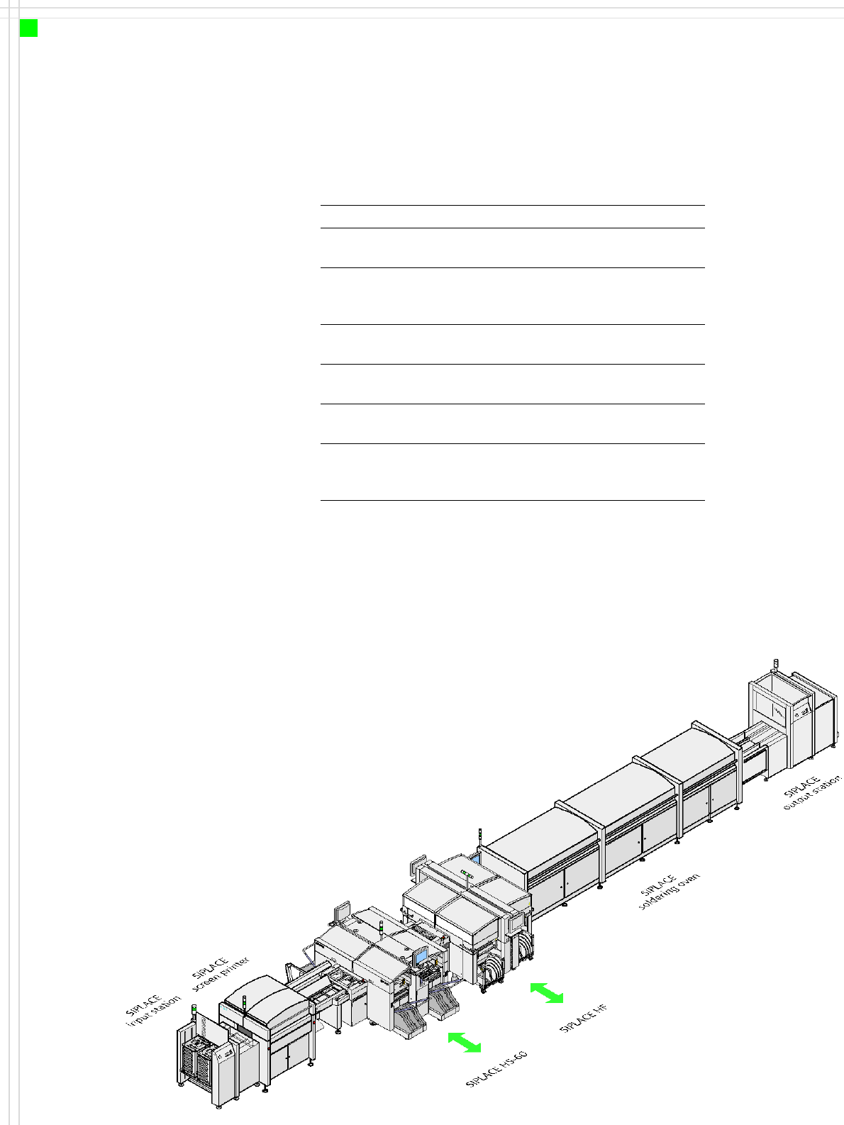
System SIPLACE SMD placement lines
Placement
modules
SIPLACE HF / SIPLACE HS-60 / SIPLACE
S-27 HM / F5 HM
Peripheral
modules
Input/output stations, screen printers,
soldering ovens, inspection stations, etc,
available from SIEMENS A&D EA
Component
range
0201 to 85 x 85 mm² / 125 x 10 mm²
max. 200 x 125 ² mm² (with restrictions)
PCB conveyor Single and dual conveyor with automatic
width adjustment unit
Placement
rate
Depends how modules are connected in
series
Space
required
4 m² per S module,
6.7 m² per HF and HF/3 module,
7.5 m² per HS module
9
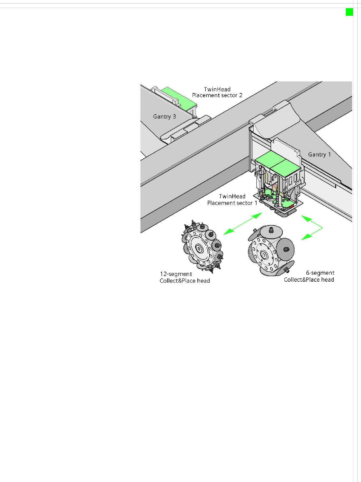
Placement Heads
Head Modularity
Innovation
•TwinHead picks up two
components at the same
time using the Pick & Place
principle
→ increased speed when
placing large components
→ greater flexibility due to
broader range of compo-
nents
• Head modularity
→ A simple placement
head change adapts the
machine to the current
production requirements
• Reconfiguration kit
→ Local placement head
change
Description
One key advantage of the
SIPLACE machines is its head
modularity. The placement
heads on the HF machines
are configurable:
Placement areas 1 and 2
• 12-segment Collect &
Place head or
• 6-segment Collect & Place
head or
•TwinHead
If you order a SIPLACE HF
placement system, you can
choose between a 6-segment
C&P head, a 12-segment
C&P head or a TwinHead.
The placement system will be
configured and supplied as
per your order.
Also available is a reconfig-
uration kit if you wish to
change the placement head
locally. This package contains
the appropriate nozzle
changers, assembly parts,
cables, etc, in addition to the
placement head.
Head modularity provides an
easy way to match the place-
ment system to your produc-
tion needs without having to
invest in additional
machines.