西门子SIPLACE HF-设备参数_US.pdf - 第6页
6 Machine Description Overview Upgrade The following opti ons are available to extend th e machine's functionalit y: • Additional component changeover ta bles increase mac hine utili za- tion since set-up times can …
5
Machine Description
Overview
Innovation
• Linear drives on every
gantry → faster accelera-
tion and braking of X and
Y gantries → higher place-
ment rate
• Gantry extensions con-
structed from carbon fiber
composite, 5 times lighter
than steel and twice as
rigid → increased speed
and accuracy
•TwinHead places two
components at the same
time using the Pick & Place
principle
→ increased speed when
placing large components
→ greater flexibility due to
broader range of compo-
nents
• TwinHead component
vision camera with 50 mm
x 40 mm field of view →
maximum speed together
with more reliable detec-
tion of even complex com-
ponents such as CCGA or
flip chip
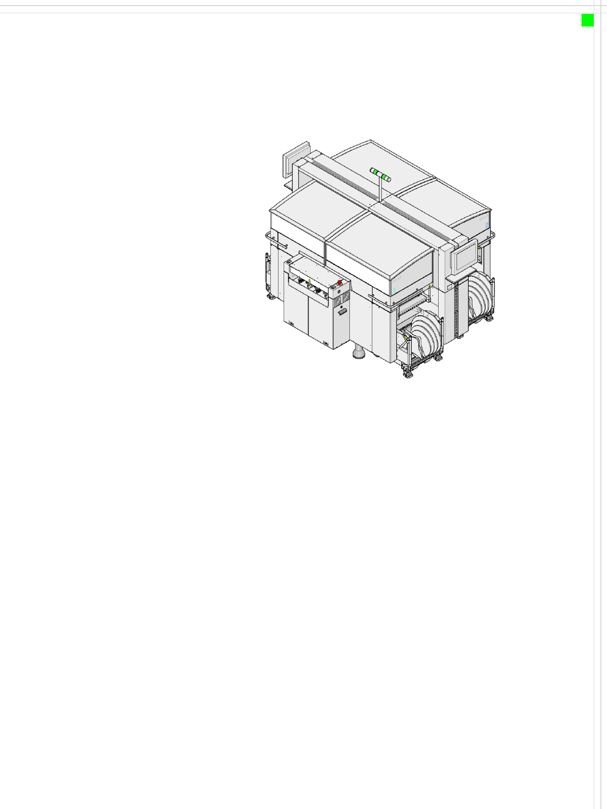
Description
The SIPLACE HF placement
system is particularly suitable
for applications that demand
a high level of flexibility and
utmost precision. Two place-
ment methods are used:
•the Collect & Place
methods for high-speed
placement of standard
components ( see diagram
on page 6)
•the Pick & Place methods
for fast placement of spe-
cial fine-pitch and super-
fine pitch components
The HF/placement system
has two gantries driven by
linear motors. The gantries
can be quickly and accurately
positioned in the X and Y
directions. There is a place-
ment head on each gantry.
The following placement
head configurations are
possible:
Placement areas 1 and 2
• 12-segment Collect &
Place head or
• 6-segment Collect & Place
head or
•TwinHead
The head modularity prin-
ciple allows the placement
heads to be reconfigured to
suit changing requirements.
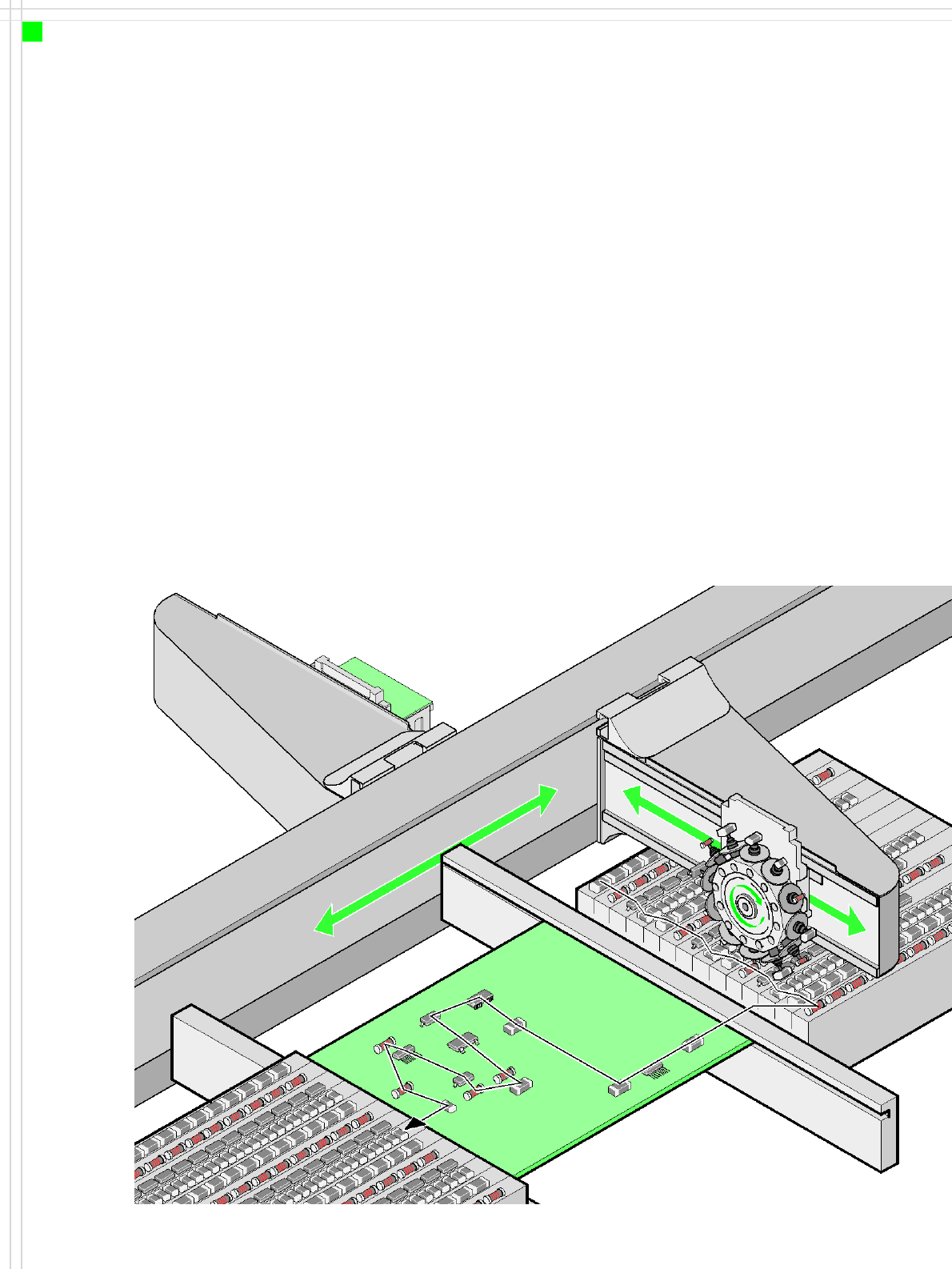
The moving head picks up
the components from their
stationary feeder, and places
them on the PCB, which is
also stationary. This proven
SIPLACE principle has many
advantages:
• Short down times for refill-
ing or splicing
• Even the smallest compo-
nents (e.g. 0201) are
picked up reliably
• The components cannot
slip on the PCB
• Minimal traversing paths
High flexibility, cost-effec-
tiveness and set-up reliability
guarantee that the SIPLACE
HF placement system will be
highly productive. The mini-
mal down times increase uti-
lization, thus further
increasing productivity.
6
Machine Description
Overview
Upgrade
The following options are
available to extend the
machine's functionality:
• Additional component
changeover tables
increase machine utiliza-
tion since set-up times can
be reduced by carrying out
preliminary set-up off the
machine.
•The dual conveyor also
increases machine utiliza-
tion by eliminating non-
productive PCB transport
times.
• Automatic nozzle chang-
ers speed up and optimize
the nozzle configuration
process.
• PCB barcode scanners
allow the production set-
up to be changed over
when triggered by a new
product.
• Component barcode scan-
ners optimize the set-up
and refill checks.
• Large and sensitive fine-
pitch components can be
supplied in trays by two
matrix tray changers.
• The productivity lift imple-
ments the concept of par-
allel placement, and thus
improves the ratio be-
tween productive and
non-productive times.
Placement principle
Collect & Place

7
Machine Description
Technical Data
Types of placement head SIPLACE TwinHead (TH)
6-segment Collect & Place head (C&P6)
12-segment Collect & Place head (C&P12)
Number of gantries 2
Placement rate
(benchmark)
Placement area 1 Placement area 2
C&P12 C&P12 28,000 comp./h
C&P12 C&P6 23,300 comp./h
C&P6 C&P6 18,600 comp./h
C&P12 TH 17,700 comp./h
C&P6 TH 13,000 comp./h
TH TH 7,400 comp./h
Range of components 0.6 x 0.3 mm² (0201) to 85 x 85 mm² / 125 x 10 mm²
max. 200 x 125 mm² (with restrictions)
Component height C&P12: 6 mm
C&P6: 8.5 mm
TH: 25 mm (When using the multi-color camera, the height
reduces to 18.3 mm.)
Placement accuracy C&P12: ± 60 µm standard, ± 55 µm DCA, ± 0.7° / (4 σ)
C&P6: ± 60 µm standard, ± 55 µm DCA, ± 0.3° / (4 σ)
TH: ± 35 µm standard, ± 30 µm FC, ± 0.07° / (4 σ)
PCB format
(LxW)
PLEASE NOTE:
With PCB widths > 450 mm
make sure that the peripheral
modules are also able to pro-
cess these widths.
Single conveyor
50 x 50 mm² to 450 x 508 mm²
50 x 80 mm² to 610 x 508 mm² ("Long board" option)
Dual conveyor
50 x 50 mm² to 450 x 250 mm²
50 x 80 mm² to 610 x 250 mm² ("Long board" option)
Dual conveyor in Single conveyor mode
50 x 50 mm² to 450 x 450 mm²
50 x 80 mm² to 610 x 450 mm² ("Long board" option)
PCB thickness 0.3 - 4.5 mm (thicker PCBs on request)
Feeding capacity 180 tracks, width 8 mm (60 3 x 8 mm S feeder)
120 tracks, width 8 mm (60 2 x 8 mm S feeder)
60 tracks, width 12 or 16 mm (60 12/16 mm S feeder)
40 tracks, width 24 or 32 mm (40 24/32 mm S feeder)
28 tracks, width 44 mm (28 44 mm S feeder)
24 tracks, width 56 mm (24 56 mm S feeder)
20 tracks, width 72 mm (20 72 mm S feeder)
16 tracks, width 88 mm (16 88 mm S feeder)
Component feeding 4 component changeover tables with tape roll holders and integral
waste containers, 15 slots, 30 mm wide, per changeover table or
up to 2
matrix tray changers, rather than component changeover
tables
Feeder module types Tapes, bulk cases, stick magazines, application-specific OEM
feeders, surftape feeders (8, 12, 16 mm), manual trays
Electrical ratings and com-
pressed air specification
see page 32
Dimensions and set-up condi-
tions
see page 34