西门子SIPLACE HF-设备参数_US.pdf - 第23页
23 Component Feeding Component Ch angeover Table Innovation • Automatic co upling an d uncoupling • Combine d interface for both electric al and pn eu- matic conn ect ions → Cable s no longe r have to be connec ted and d…
22
PCB Conveyor
PCB Barcode for Product-Controlled
Production (Option)
Label dimensions Stroke width (W): 0.19 < W ≤ 0.3 mm (corresponds to high and medium
density), sroke length: ≥ 4 mm, length of the barcode template win-
dow: ≤ 90 mm
Recommended
label colors
Coding: black, dark green, dark blue, background: white, beige, yellow,
orange (contrast ratio > 70% to DIN 66236
Code types Code 39, Code 128 / EAN 128, Codabar, 2/5 IATA 2/5 industrial, 2/5 inter-
leaved, UPC, EAN, Pharma Code, EAN Addendum (others available on
request), max. 25 digits, a barcode filter may be defined
Laser scanner
safety
Laser diode 670 nm (red) / 1.2 mW
Laser protection class 2, degree of protection IP65
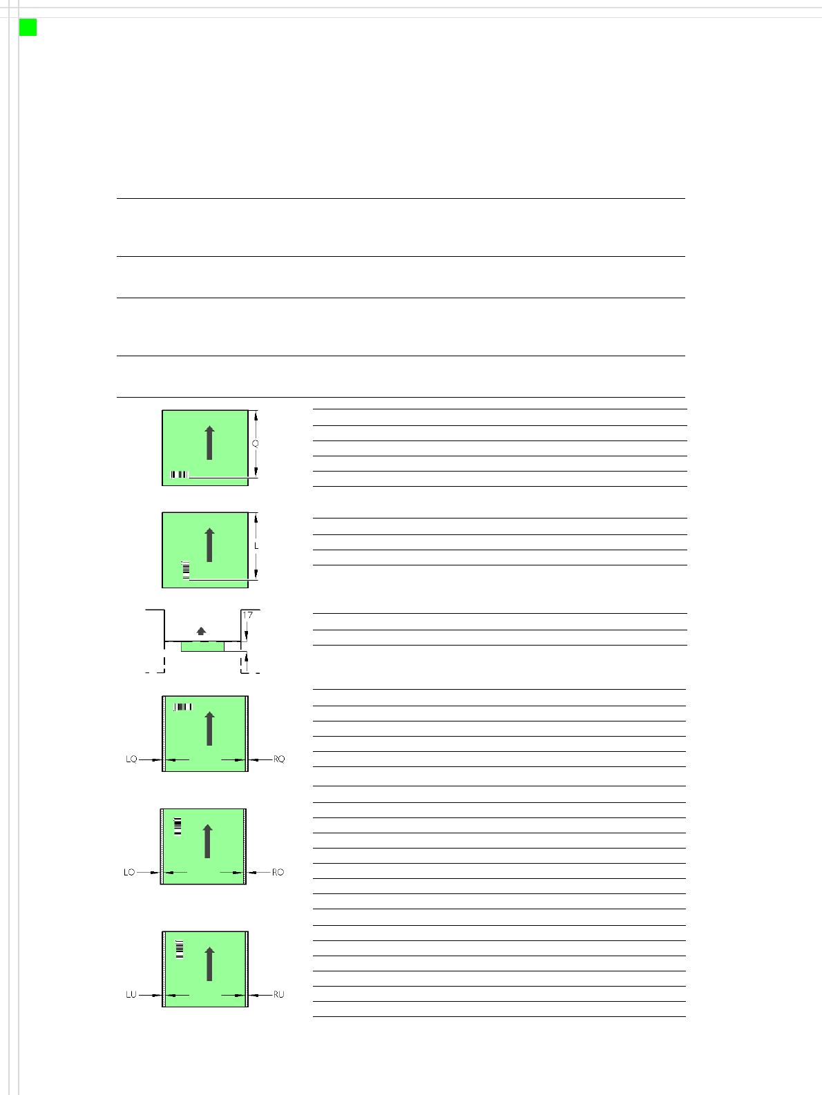
PCB barcode reader Q [mm]
2D on top 390
1D on top 390
2D on bottom 430
1D on bottom 430
PCB barcode reader L [mm]
1D on top 320 - 350
1D on bottom 380 - 410
PCB barcode reader PCB rear projection [mm]
2D on bottom (dual conveyor) 17
PCB barcode reader LQ [mm] RQ [mm]
2D on top 3 3
1D on top 3 3
2D on bottom 5 5
1D on bottom 5 5
PCB dimensions/conveyor LO [mm] RO [mm]
460 mm SC 3 20
508 mm SC 3 44
216 mm DC1 3 24
250 mm DC1, 450 mm SM1 3 58
216 mm DC2 3 3
250 mm DC2, 450 mm SM2 3 3
PCB dimensions/conveyor LU [mm] RU [mm]
460 mm SC 20 3
508 mm SC 44 3
216 mm DC1 3 3
250 mm DC1, 450 mm SM1 3 3
216 mm DC2 24 3
250 mm DC2, 450 mm SM2 58 3
SC - Single conveyor, DC1/2 - Dual conveyor, track 1/2, SM1/2 - Dual conveyor in Single conveyor mode, track 1/2
Downstream
machine
Upstream
machine
PCB
PCB barcode scanner 1D on top
PCB barcode scanner 1D bottom
23
Component Feeding
Component Changeover Table
Innovation
• Automatic coupling and
uncoupling
• Combined interface for
both electrical and pneu-
matic connections →
Cables no longer have to
be connected and discon-
nected manually
• Precise alignment → par-
ticularly important for
small components
• Easy to convert for other
PCB transport heights
• Tape reel diameter from 7“
up to 19“ → high flexibility
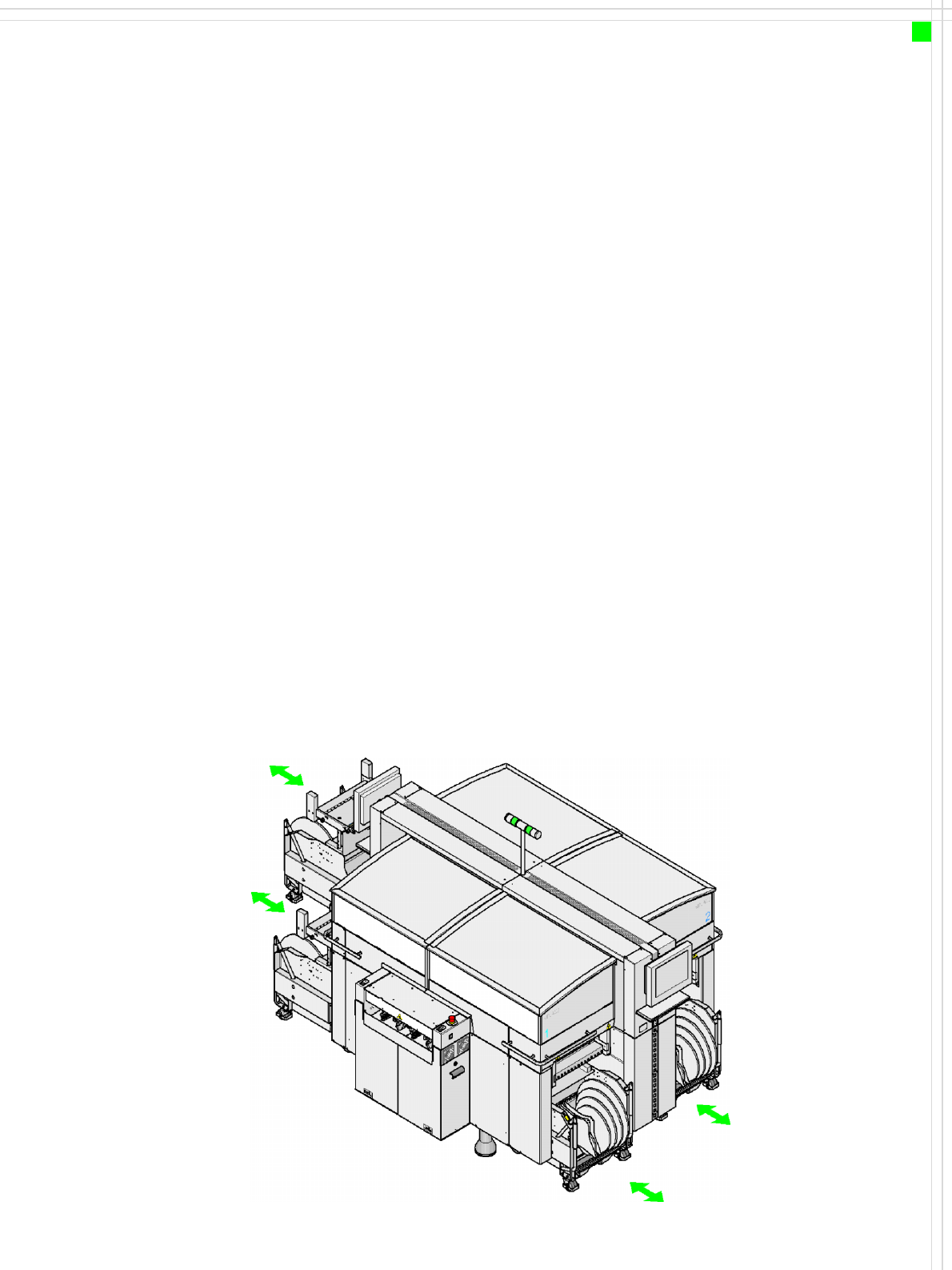
Description
Up to four component
changeover tables may be
coupled to the machine.
Optionally, a matrix tray
changer may be installed at
locations 2 or 4.
The component changeover
tables are stand-alone mod-
ules that can be set up at an
external set-up area with
feeders. In this way, changes
only interrupt the production
process for a short time. The
chassis runs smoothly and is
easy to maneuver. There are
pockets for holding set-up list
print-outs on both sides of
the component changeover
table. The operator has un-
hindered access to the docu-
ments, even during pro-
duction.
The component feeder table
has a capacity of up to 15
locations for 30 mm wide
feeders. The total capacity
with four component
changeover tables is thus
180 x 8 mm tracks.
Bulk case feeders and vibra-
tory stick feeders may be set
up in addition to the tape
feeders. Dummy feeders are
used at unassigned locations
to protect the operators.
The communication unit
sends the necessary voltages
and control signals to the
feeders.
The component feeders are
at rest during the placement
process, which means that
components can be refilled
(in sticks, for example) and
tapes may be spliced without
stopping the machine.
An optional component bar-
code reader can be used to
scan and check the barcodes
on the tape reels, thus guar-
anteeing that the compo-
nents are allocated to the
correct tracks.
Location 1
Location 2
Location 3
Location 4
24
Component Feeding
Component Changeover Table
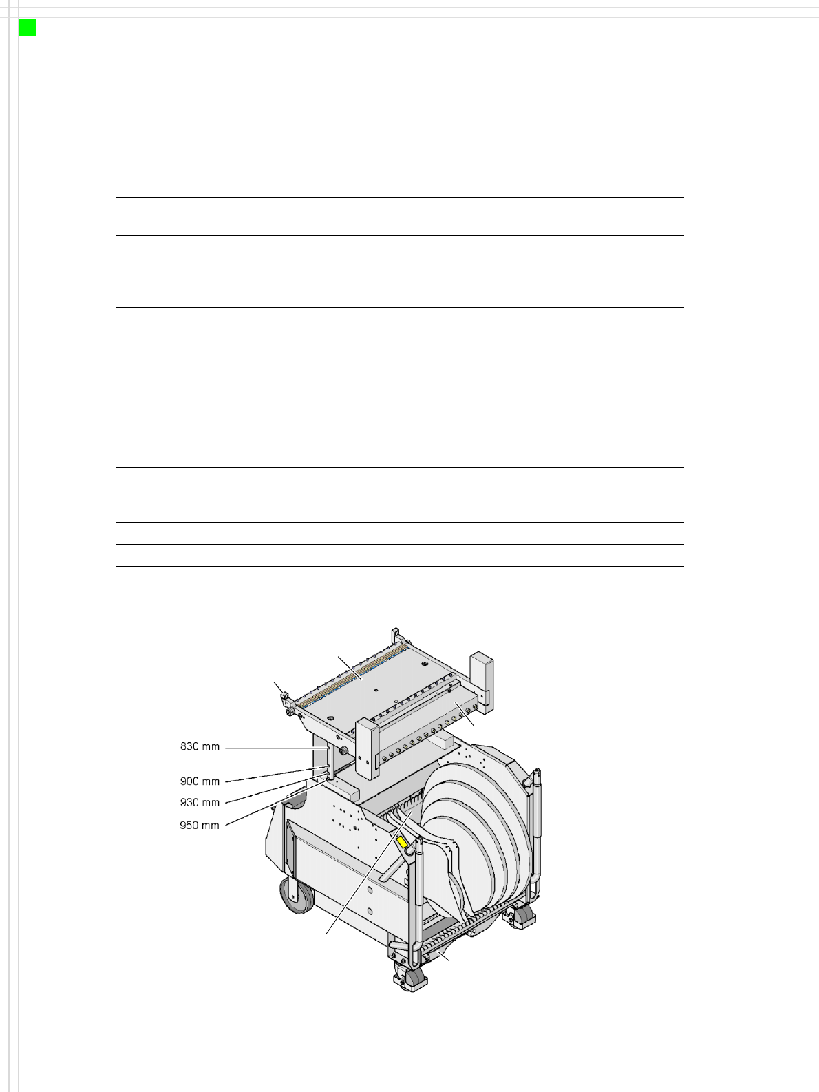
Technical Data
Length x width 728 x 592 mm²,
752 x 592 mm² (with waste container)
Height 830 mm for 830 mm PCB transport height
900 mm for 900 mm PCB transport height
930 mm for 930 mm PCB transport height
950 mm for 950 mm PCB transport height
PCB transport height 830 mm ± 15 mm (standard)
900 mm ± 15 mm (SMEMA)
930 mm ± 15 mm (SMEMA)
950 mm ± 15 mm (SMEMA)
Weight
without feeder
with feeders at every location
with compressed air supply for bulk case
feeder and adapter for the 3rd tape reel
approx. 85 kg
approx. 125 kg
approx. 150 kg
Reel diameter
standard
maximum
up to 432 mm (17“)
483 mm (19“)
Feeder locations max. 15
Changeover time less than 1 min.
Component feeder table
Centering
Communication unit
Waste container
for pieces of used tape
Tape container