西门子SIPLACE HF-设备参数_US.pdf - 第27页
27 Component Feeding Dummy Feeders Dang er To ensure that your SIPLACE placement m achine runs safe- ly, a fe eder mu st be ass ig ned to every loca tion on the c om- ponent chan geover tabl e. If you do not have enough …
26
Component Feeding
Bulk Case Feeder
Technical data
a) Fiducial for feeder position detection
Bulk case feeder
a)
Packaging form Bulk case
Feeder rails Chip 0402 CO height: 0.35 mm
Chip 0402 CO height: 0.50 mm
Chip 0603 CO height: 0.45 mm
Chip 0603 CO height: 0.80 mm
Chip 0805 CO height: 0.45 mm
Chip 0805 CO height: 0.60 mm
Chip 0805 CO height: 0.85 mm
Chip 0805 CO height: 1.25 mm
Micro-Melf: 1.05 ± 0.05 mm
Mini-Melf: 1.4 ± 0.1 mm
Location 1 location for 2 different compo-
nent types
Vibratory stick feeder,
type 3
with control circuit
Number of tracks and
width
3 x 9.5 mm
2 x 15 mm
1 x > 15 mm
1 x 30 mm
Location 1 location
Description
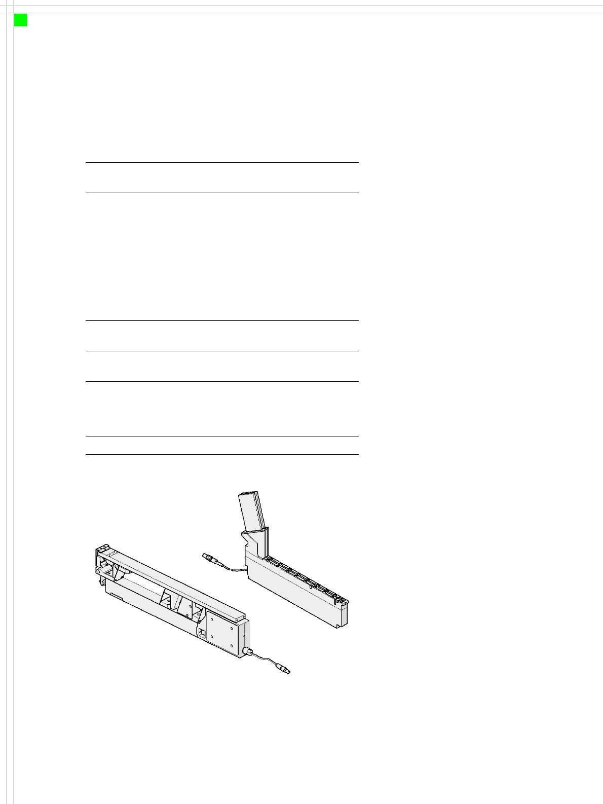
The SIPLACE bulk case feeder
processes bulk cases on two
tracks. It feeds rectangular
and round, passive compo-
nents. The PCB magazines
(bulk cases) are simply re-
placed for refilling - without
stopping the machine.
The module essentially con-
sists of the basic element plus
two feeder rails and PCB mag-
azines to suit the component
type and height. The compo-
nents are separated and fed
along the rails by compressed
air.
The principle of the fixed
component pocket has prov-
en most suitable, even when
using bulk cases: the vibra-
tions that occur with other
placement machine concepts
can greatly impair the com-
ponent quality due to fric-
tion, for example.
The stationary component
feeder also has significant
advantages with stick maga-
zines: the universal vibratory
stick feeder can be refilled
during placement.
Bulk case feeder
Vibratory -
stick feeder, type 3
27
Component Feeding
Dummy Feeders
Danger
To ensure that your SIPLACE
placement machine runs safe-
ly, a feeder must be assigned
to every location on the com-
ponent changeover table. If
you do not have enough
feeders, then you should use
dummy feeders as space
holders.
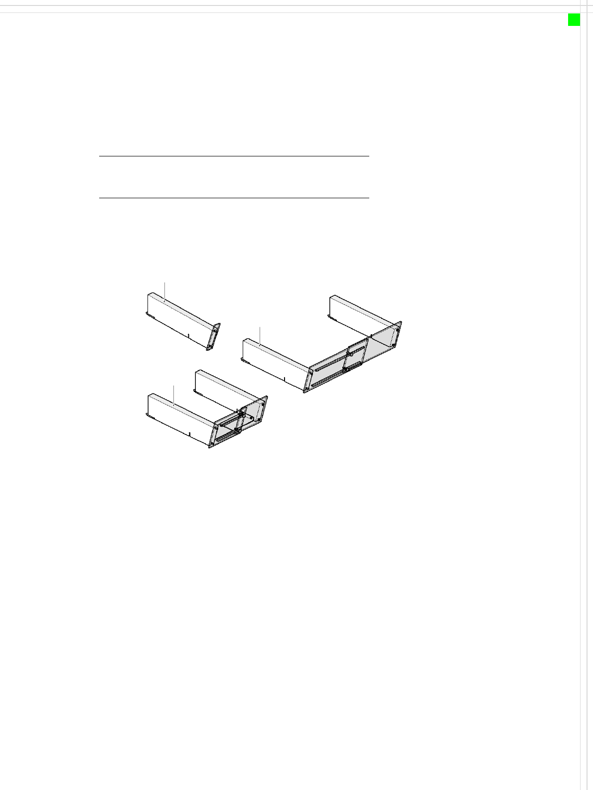
The following dummy feeders may be used:
SIPLACE dummy feeder for 1 location
SIPLACE dummy feeder for 6 - 10 locations
SIPLACE dummy feeder for 11 - 20 locations
Dummy feeder for 1 location
Dummy feeder for
6 - 10 locations
Dummy feeder for
11 - 20 locations

28
Component Feeding
Manual Trays
Manual tray
Component feeder table
Waffle tray
Description
The manual tray is a device
for holding JEDEC trays used
to supply components. The
waffle trays are changed
manually. The manual tray is
placed on the component
feeder table just like a feeder.
There are two different ver-
sions of the waffle tray: one
fills 5 locations, while the
other takes up 9 locations on
the component feeder table.
On the SIPLACE HF, the man-
ual tray is used at location 2
or location 4. This option is
recommended if there are
only a few types of compo-
nent to be placed from a tray.
Technical data
Manual tray - possible positions
Sizes 136 x 360 mm²; requires 5 locations
260 x 360 mm²; requires 9 locations
Max. tray
height
12.5 mm, including component
Parts Waffle tray carrier
Tray holder
JEDEC waffle
tray
Directly in the waffle tray carrier
136 mm wide