AN353423548483en-000201.pdf - 第20页
7 Messaging 7.1 Implicit Messaging (Cyclic Operation) This section lists the requirements related to cyclic (implicit messaging) services for the EtherNet/IP Card. The minimum cyclic inter- val is 1 ms. All data is in li…
6 Operation
6.1 Requirements for Successful Operation
The EtherNet/IP Card is conformance-tested to ODVA. For successful operation, the scanner must also support all functions and
interfaces described in this manual.
N O T I C E
The available features and parameter details may vary according to the model and software version of the soft starter. Refer to
the VLT® Soft Starter MCD 600 Operating Guide for details of parameters and supported features.
6.2 Device Classification
The EtherNet/IP Card is an I/O adapter and must be managed by an I/O scanner over Ethernet.
The EtherNet/IP Card supports both implicit (cyclic) and explicit (acyclic) messaging.
6.3 Ensuring Safe and Successful Control
Data written to the device remains in its registers until the data is overwritten or the device is reinitialized. If the soft starter is con-
trolled via parameter 7-1 Command Override or is disabled via the reset input (terminals RESET, COM+), fieldbus commands should
be cleared from the registers. If a command is not cleared, it is re-sent to the soft starter once fieldbus control resumes.
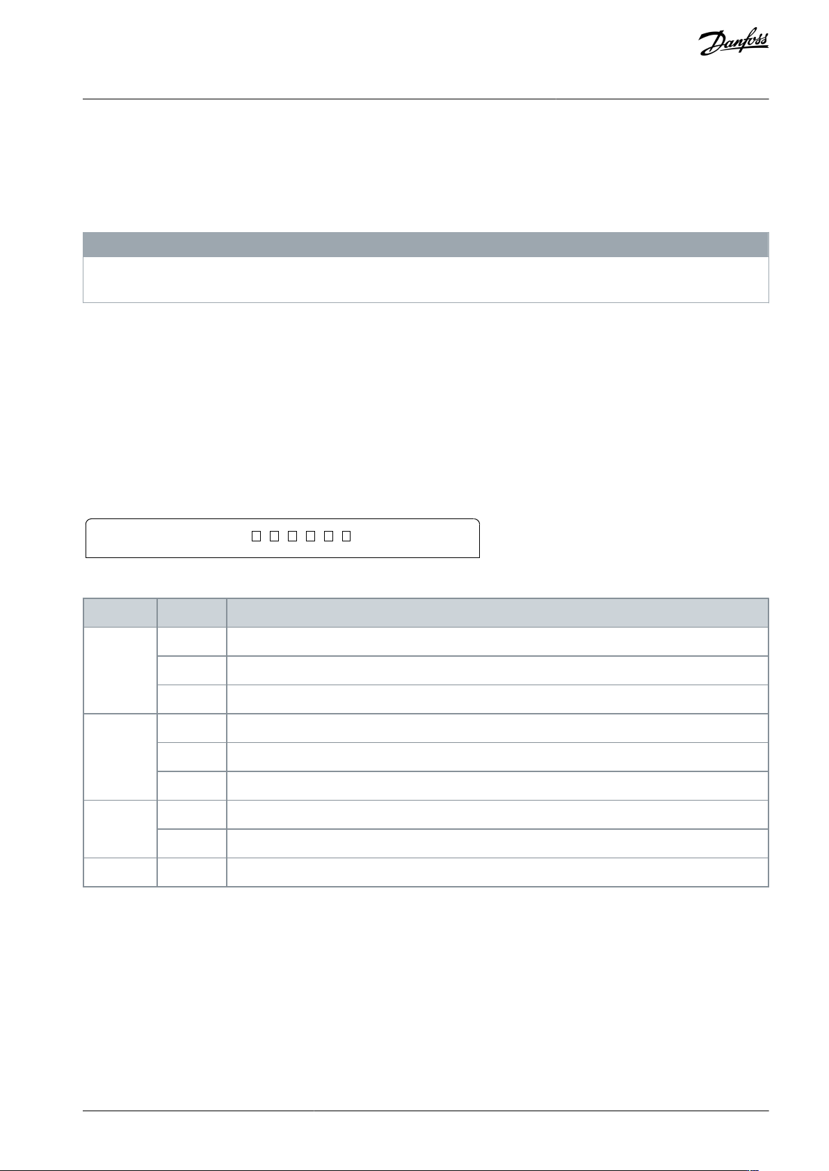
6.4 Feedback LEDs
Port 1 Port 2
Keypad
LINK 2
TX/RX2
LINK 1
TX/RX1
ERROR
STATUS
e77ha742.10
Table 3: LED Descriptions
LED name
LED state
Description
Error
Off
The device is not powered up or the the device is powered up and has received an IP address.
Flashing
Connection timeout.
On
Duplicate IP address.
Status
Off
The device is not powered up or the the device is powered up and has received an IP address.
Flashing
The device has obtained an IP address but has not established any network connections.
On
Communication has been established.
Link x
Off
No network connection.
On
Connected to a network.
TX/RX x
Flashing
Transmitting or receiving data.
AN353423548483en-000201 / 130R0945 | 19Danfoss A/S © 2022.10
Operation
EtherNet/IP Card
Installation Guide
7 Messaging
7.1 Implicit Messaging (Cyclic Operation)
This section lists the requirements related to cyclic (implicit messaging) services for the EtherNet/IP Card. The minimum cyclic inter-
val is 1 ms. All data is in little endian format.
7.1.1 Assembly Objects
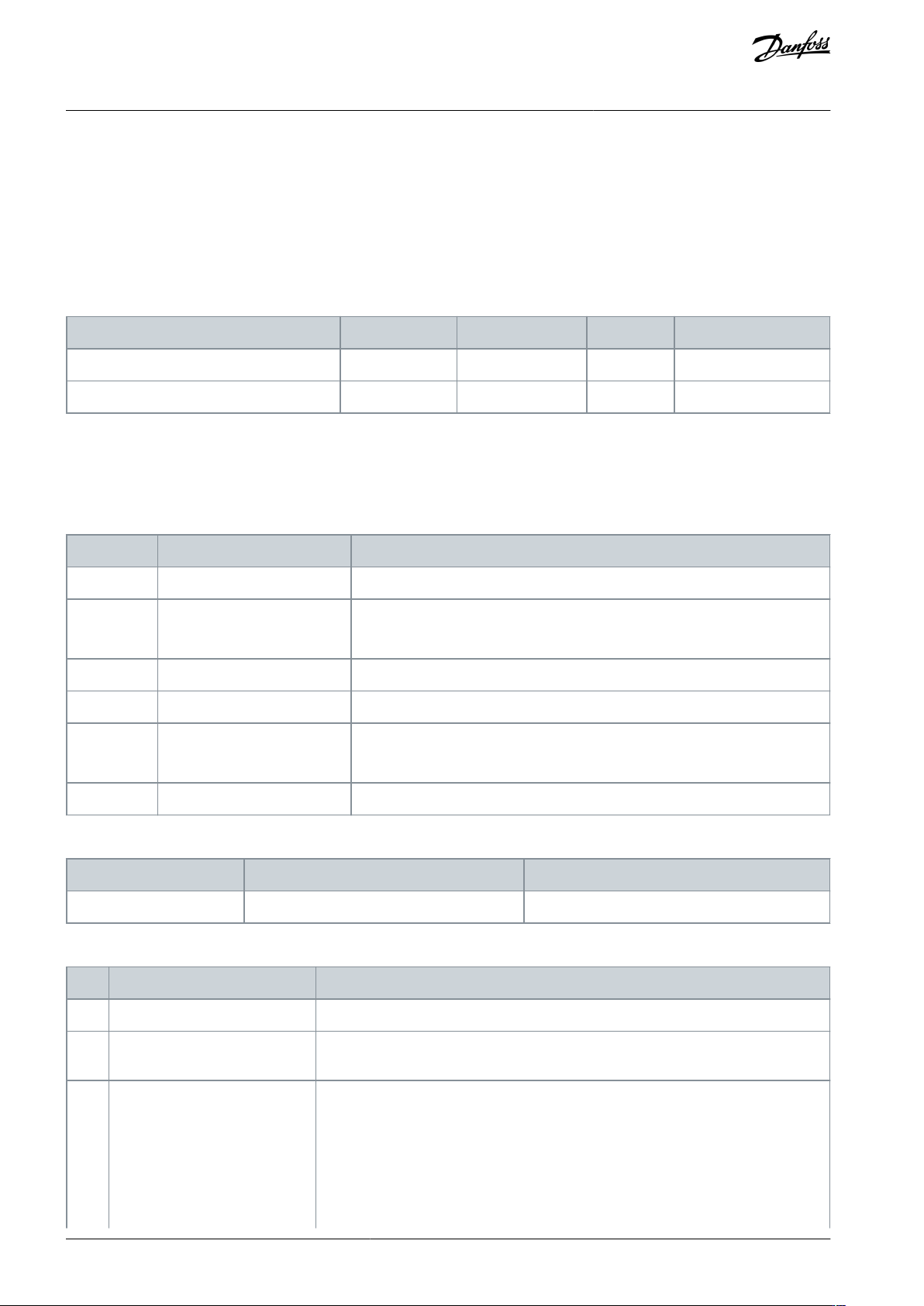
Table 4: Supported Assembly Objects
Description
Class
Instance
Type
Maximum size
Output (Originator⇒Target)
04d (0x04)
104d (0x68)
Integer
2 (4 bytes)
Input (Target⇒Originator)
04d (0x04)
154d (0x9A)
Integer
6 (12 bytes)
7.1.2 Control Commands (Assembly Instance 104d)
To send control data from the scanner to the soft starter, use assembly class 04d (0x04), assembly instance 104d (0x68), attribute
03d (0x03).
7.1.2.1 Bytes 0–1: Command
Bits
Function
Details
0–5
Reserved
Must be 0.
6
Run
0 = Stop command
1 = Start command
7
Reset
Changing this bit from 0 to 1 resets a trip.
8–12
Reserved
Must be 0.
13
Motor set select
0 = Use primary motor set when starting.
1 = Use secondary motor set when starting.
14–15
Reserved
Must be 0.
7.1.2.2 Bytes 2–3: Reserved
Bits
Function
Details
0–15
Reserved
Must be 0.
7.1.2.3 Command Examples
Byte
Value
Description
0
0b01000000 (64d, 0x40)
Command: Start the soft starter.
1
0b00000000 (00d, 0x00) or
0b00100000 (32d, 0x20)
Command: Select primary or secondary motor settings when starting.
0
0b10000000 (128d, 0x80)
Command: Reset the soft starter.
AN353423548483en-000201 / 130R094520 | Danfoss A/S © 2022.10
Messaging
EtherNet/IP Card
Installation Guide
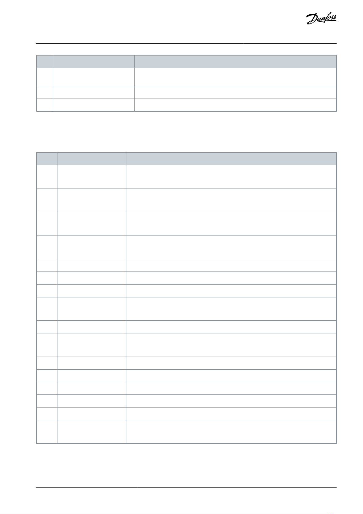
Byte
Value
Description
The reset only occurs when the previous reset bit is 0, otherwise the value of 1 is ig-
nored.
0
0b11000000 (192d, 0xC0)
Command: Reset and start the soft starter.
0
0bX0000000 (00d, 0x00)
Command: Stop the soft starter.
7.1.3 Status Information (Assembly Instance 154d)
To retrieve status data from the soft starter, use assembly class 04d (0x04), assembly instance 154d (0x9A), attribute 03d (0x03).
7.1.3.1 Bytes 0–1: Starter State
Bits
Function
Details
0
Ready
0 = Not ready
1 = Ready to start
1
Operating mode
0 = Program mode
1 = Operating mode
2
Running
0 = Not ready, ready to start, or tripped
1 = Starting, Running, Stopping, or Jogging
3
Trip
0 = Not tripped
1 = Tripped
4
Jog forward
1 = Jog forward
5
Jog reverse
1 = Jog reverse
6
Reserved
7
Warning
0 = No warning
1 = Warning
8
Ramping
1 = Running (full voltage at the motor)
9
Command source
0 = Remote LCP, digital input, clock
1 = Network
10
Reserved
11
Reserved
12
Reserved
13
Reserved
14
Reserved
15
Temperature limit
0 = Motor operating within thermal capacity (thermal model)
1 = Motor operating above thermal capacity (thermal model)
AN353423548483en-000201 / 130R0945 | 21Danfoss A/S © 2022.10
Messaging
EtherNet/IP Card
Installation Guide