AN353423548483en-000201.pdf - 第34页
10 Network Design 10.1 Star Topology In a star network, all controllers and devices connect to a central network switch. e77ha628.10 Illustration 3: Example of Star Topology 10.2 Line Topology In a line network, the cont…

1.
2.
3.
9 Ground Fault Protection
9.1 Overview
N O T I C E
Ground fault protection is only available on ground fault enabled option cards with soft starters running a compatible version of
software. Contact the supplier for assistance.
The EtherNet/IP Card can detect ground current and trip before the equipment is damaged.
Ground fault protection requires a 1000:1 or 2000:1 current transformer (not supplied). The CT should be rated 1 VA or 5 VA. The soft
starter can be configured to trip at 1–50 A. If ground fault current rises above 50 A, the soft starter trips immediately.
Parameter 40-3 Ground Fault Trip Active selects when ground fault protection is active.
9.2 Connect the CT to the Ground Fault Inputs
To use ground fault protection, a common-mode current transformer (CT) must be installed around all 3 phases.
Procedure
Use a 1000:1 or 2000:1 CT with a rating of 1 VA or 5 VA.
Set parameter 40-5 Ground Fault CT ratio to match the CT.
Connect the CT to the ground fault terminals (G1, G2, G3).
For maximum protection, the CT should be installed on the input side of the soft starter.
9.3 Configure Ground Fault Protection Settings
Ground fault protection settings must be set in the soft starter.
Parameter
Description
Parameter 40-1 Ground Fault Level
Sets the trip point for ground fault protection.
Parameter 40-2 Ground Fault Delay
Shows the response of the EtherNet/IP Card to ground fault variation, avoiding trips due
to momentary fluctuations.
Parameter 40-3 Ground Fault Trip Active
Selects when a ground fault trip can occur.
Parameter 40-4 Ground Fault Action
Selects the response of the soft starter to the protection event.
Parameter 40-5 Ground Fault CT Ratio
Set to match the ratio of the ground current measuring CT.
AN353423548483en-000201 / 130R0945 | 33Danfoss A/S © 2022.10
Ground Fault Protection
EtherNet/IP Card
Installation Guide
10 Network Design
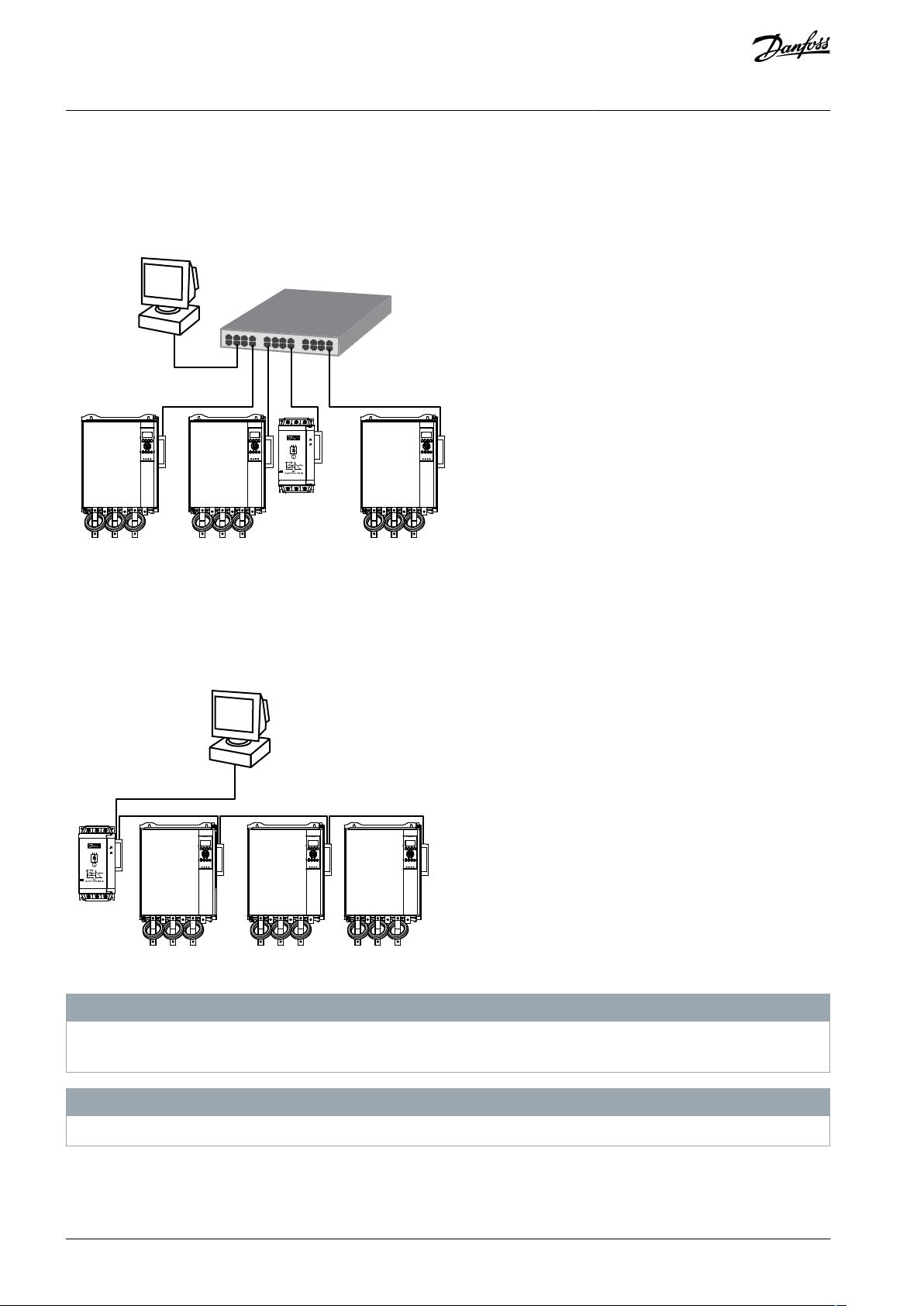
10.1 Star Topology
In a star network, all controllers and devices connect to a central network switch.
e77ha628.10
Illustration 3: Example of Star Topology
10.2 Line Topology
In a line network, the controller connects directly to 1 port of the 1
st
card. The 2
nd
Ethernet port connects to another card, which in
turn connects to another device until all devices are connected.
e77ha629.10
Illustration 4: Example of Line Topology
N O T I C E
The device has an integrated switch to allow data to pass through in line topology. The device must be receiving control power
from the soft starter for the switch to operate.
N O T I C E
If the connection between 2 devices is interrupted, the controller cannot communicate with devices after the interruption point.
AN353423548483en-000201 / 130R094534 | Danfoss A/S © 2022.10
Network Design
EtherNet/IP Card
Installation Guide
N O T I C E
Each connection adds a delay to the communication with the next device. The maximum number of devices in a line network is
32. Exceeding this number may reduce the reliability of the network.
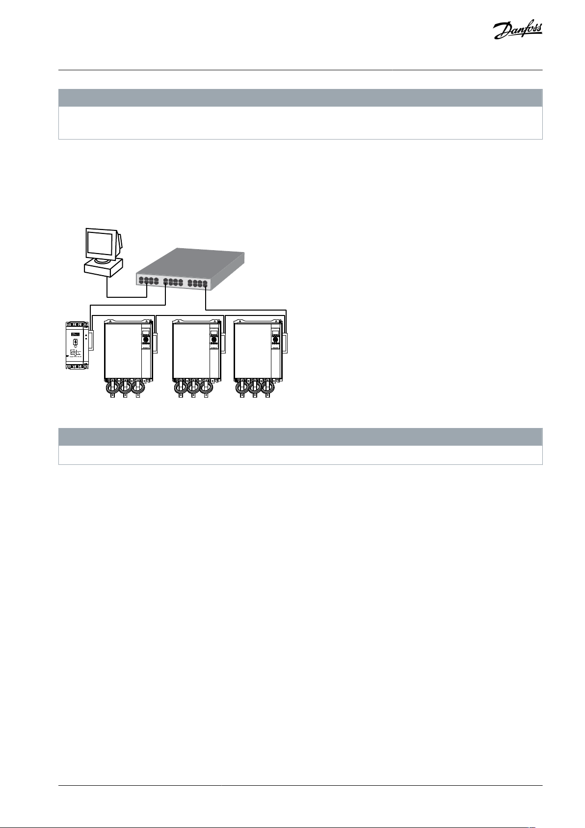
10.3 Ring Topology
In a ring topology network, the controller connects to the 1
st
card via a network switch. The 2
nd
Ethernet port of the card connects
to another device, which in turn connects to another device until all devices are connected. The final device connects back to the
switch.
The device supports beacon-based ring node configuration.
e77ha630.10
Illustration 5: Example of Ring Topology
N O T I C E
The network switch must support loss of line detection.
10.4 Combined Topologies
A single network can include both star and line components.
AN353423548483en-000201 / 130R0945 | 35Danfoss A/S © 2022.10
Network Design
EtherNet/IP Card
Installation Guide