AN353423548483en-000201.pdf - 第36页
e77ha631.10 Illustration 6: Example of Combined Topologies AN353423548483en-000201 / 130R0945 36 | Danfoss A/S © 2022.10 Network Design EtherNet/IP Card Installation Guide
N O T I C E
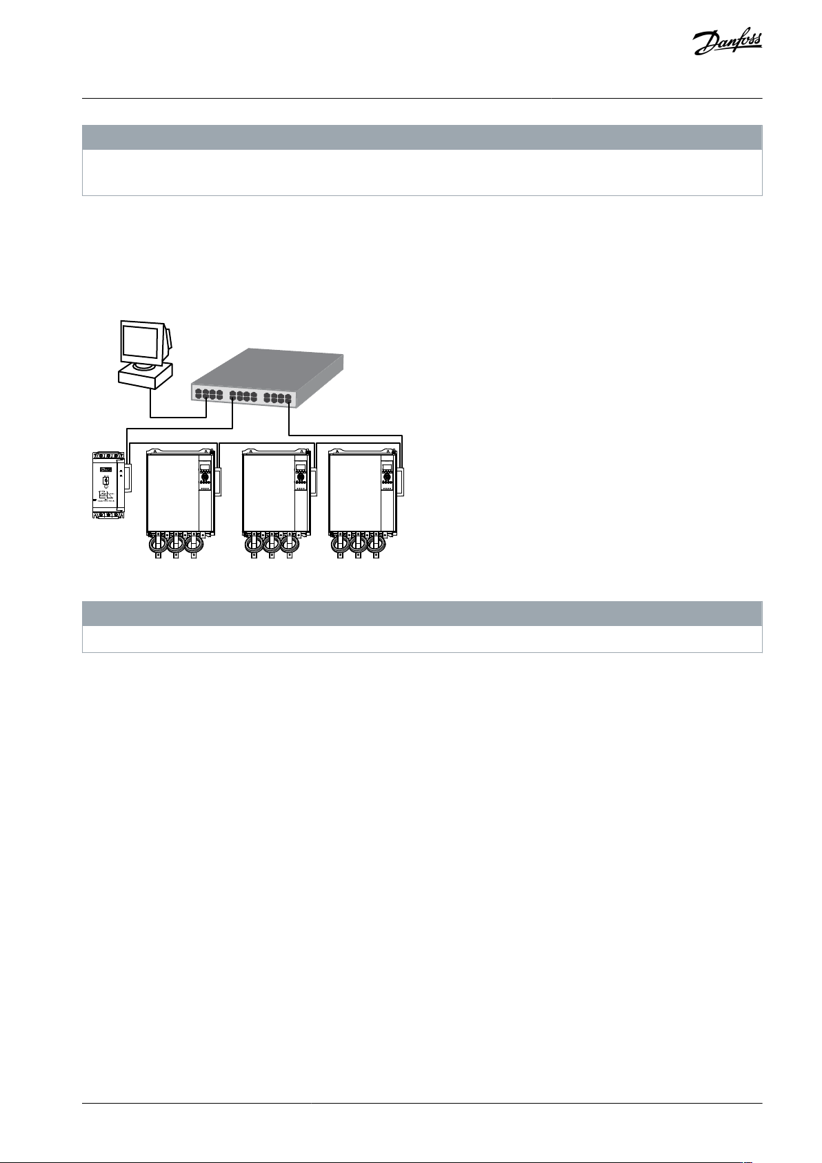
Each connection adds a delay to the communication with the next device. The maximum number of devices in a line network is
32. Exceeding this number may reduce the reliability of the network.
10.3 Ring Topology
In a ring topology network, the controller connects to the 1
st
card via a network switch. The 2
nd
Ethernet port of the card connects
to another device, which in turn connects to another device until all devices are connected. The final device connects back to the
switch.
The device supports beacon-based ring node configuration.
e77ha630.10
Illustration 5: Example of Ring Topology
N O T I C E
The network switch must support loss of line detection.
10.4 Combined Topologies
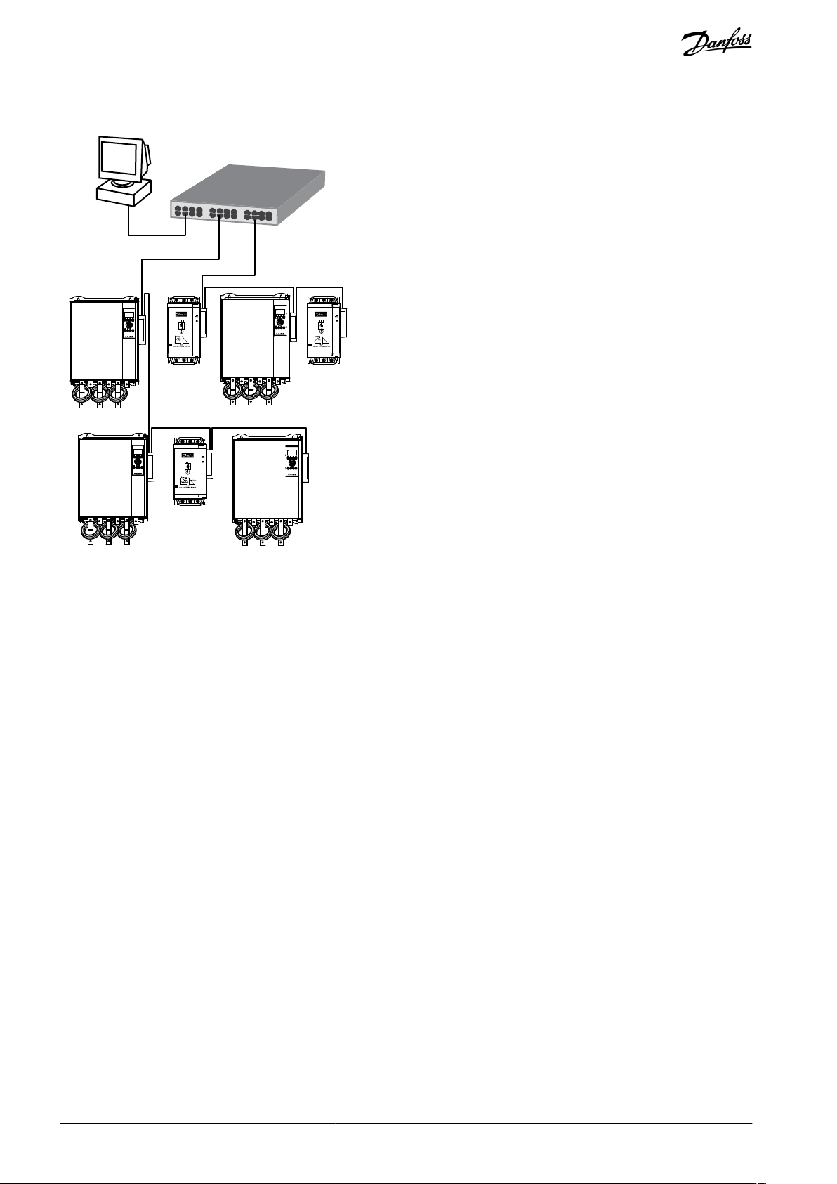
A single network can include both star and line components.
AN353423548483en-000201 / 130R0945 | 35Danfoss A/S © 2022.10
Network Design
EtherNet/IP Card
Installation Guide
e77ha631.10
Illustration 6: Example of Combined Topologies
AN353423548483en-000201 / 130R094536 | Danfoss A/S © 2022.10
Network Design
EtherNet/IP Card
Installation Guide

11 Specifications
11.1 Connections
Soft starter
6-way pin assembly
Contacts
Gold flash
Network
RJ45
11.2 Settings
IP address
Automatically assigned, configurable
Device name
Automatically assigned, configurable
11.3 Network
Link speed
10 Mbps, 100 Mbps (auto-detect)
Full duplex
Auto crossover
11.4 Power
Consumption (steady state, maximum)
35 mA@24 V DC
Reverse polarity protected
Galvanically isolated
11.5 Certification
RCM
IEC 60947-4-2
CE
EN 60947-4-2
ODVA
Illustration 7: ODVA
AN353423548483en-000201 / 130R0945 | 37Danfoss A/S © 2022.10
Specifications
EtherNet/IP Card
Installation Guide