AN353423548483en-000201.pdf - 第9页
1. 2. • • • • • • 3 Installation 3.1 Installing the Expansion Card 1 2 e77ha739.10 Illustration 2: Installing the Expansion Card Procedure Push a small flat-bladed screwdriver into the slot in the center of the expansion…

1
Soft starter
2
Network switch
3
IoT connection (MQTT/OPC UA)
4
Industrial Ethernet connection to programmable
logic controller
5
TCP connection to VLT® Motion Control Tool MCT
10. Refer to the VLT® Motion Control Tool MCT 10
Operating Guide for connection details.
AN353423548483en-000201 / 130R09458 | Danfoss A/S © 2022.10
Introduction
EtherNet/IP Card
Installation Guide
1.
2.
•
•
•
•
•
•
3 Installation
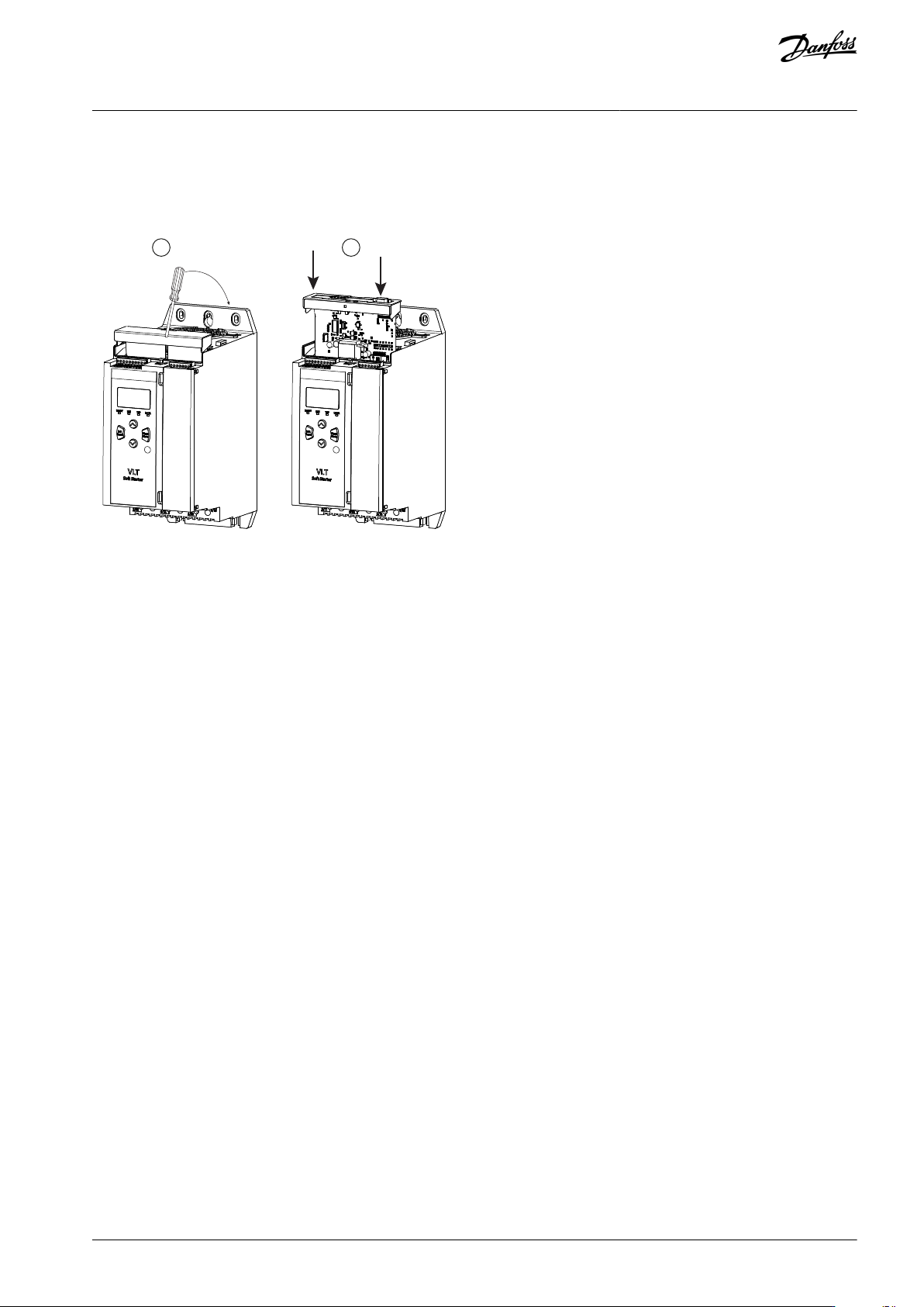
3.1 Installing the Expansion Card
1 2
e77ha739.10
Illustration 2: Installing the Expansion Card
Procedure
Push a small flat-bladed screwdriver into the slot in the center of the expansion port cover and ease the cover away from
the soft starter.
Align the card with the expansion port. Gently push the card along the guide rails until it clicks into the soft starter.
3.2 Network Connections
3.2.1 Ethernet Ports
The device has 2 Ethernet ports. If only 1 connection is required, either port can be used.
3.2.2 Cables
When connecting to the device, make sure that the cables are of 1 of the following categories:
Category 5
Category 5e
Category 6
Category 6e
3.2.3 EMC Precautions
To minimize electromagnetic interference, Ethernet cables should be separated from motor and mains cables by 200 mm (7.9 in).
If the Ethernet cable must cross motor or mains cables, the crossing should be at an angle of 90°.
3.3 Network Establishment
The controller must establish communications directly with each device before the device can participate in the network.
3.4 Addressing
Each device in a network is addressed using a MAC address and an IP address.
The device can be assigned a static IP address during configuration or can be configured to accept a dynamic IP address (via
DHCP).
The MAC address is fixed within the device and is printed on a label on the front of the device.
AN353423548483en-000201 / 130R0945 | 9Danfoss A/S © 2022.10
Installation
EtherNet/IP Card
Installation Guide
•
•
•
4 Device Configuration
4.1 Before Configuring the Device
N O T I C E
The error LED flashes whenever the device is receiving power but is not connected to a network. The error LED will flash occa-
sionally during the configuration process.
N O T I C E
At power-up, the communication card loads the IP address stored in the soft starter.
4.2 Configuration Methods
Network communication parameters for the communication card can be set via the soft starter or via the on-board web server.
The card uses a static IP address by default. To enable DHCP addressing, set parameter 12–20 DHCP to Enable or change the
setting via the on-board web server.
The IP address can be set via the programmable parameters of the soft starter.
The web server can configure the IP address and messaging settings for MQTT/OPC UA operation.
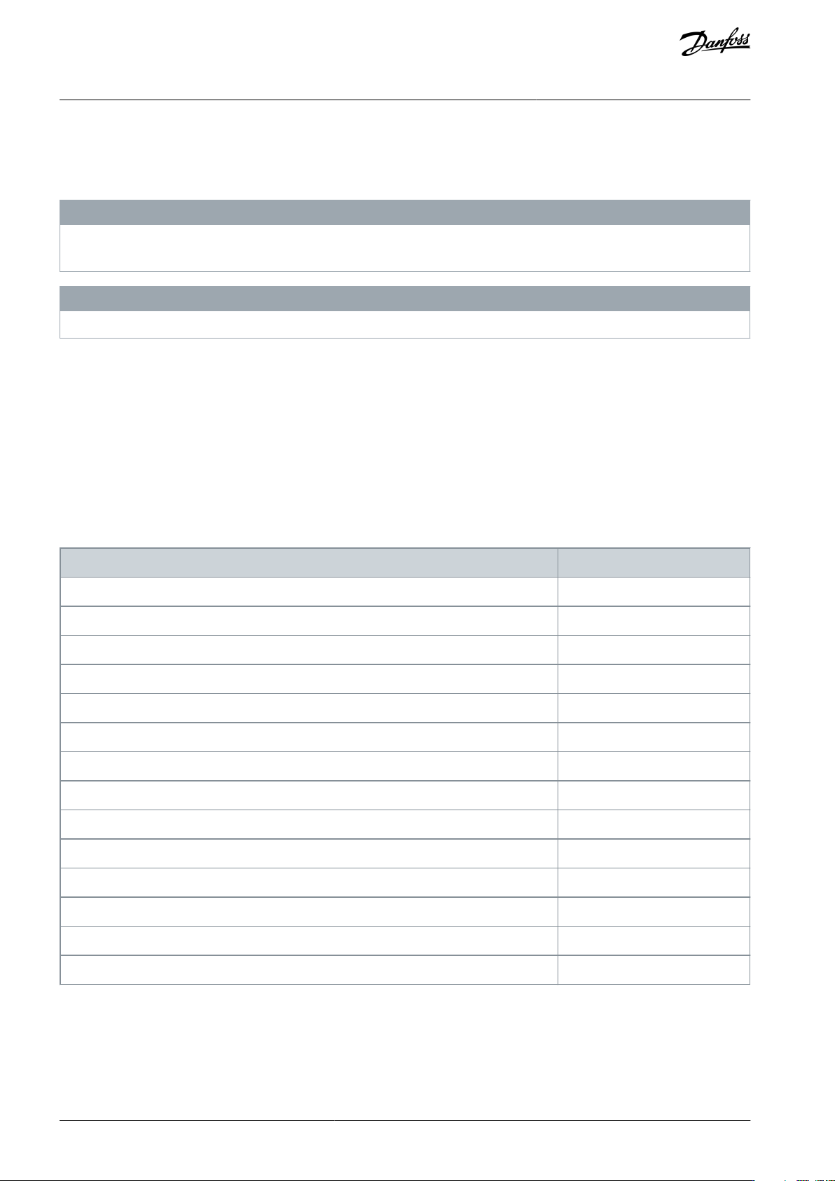
4.3 Parameters for Configuring Network Settings
Use parameters 12-8 to 12-21 to configure the network address. The parameters can be set via the Main Menu, via the Setup Tools,
or by uploading a configuration file via USB Save & Load.
Parameter
Default
12-8 Gateway Address
192
12-9 Gateway Address 2
168
12-10 Gateway Address 3
0
12-11 Gateway Address 4
100
12-12 IP Address
192
12-13 IP Address 2
168
12-14 IP Address 3
0
12-15 IP Address 4
2
12-16 Subnet Mask
255
12-17 Subnet Mask 2
255
12-18 Subnet Mask 3
255
12-19 Subnet Mask 4
0
12-20 DHCP
Disable
12-21 Location ID
0
AN353423548483en-000201 / 130R094510 | Danfoss A/S © 2022.10
Device Configuration
EtherNet/IP Card
Installation Guide