AN353423548483en-000201.pdf - 第27页
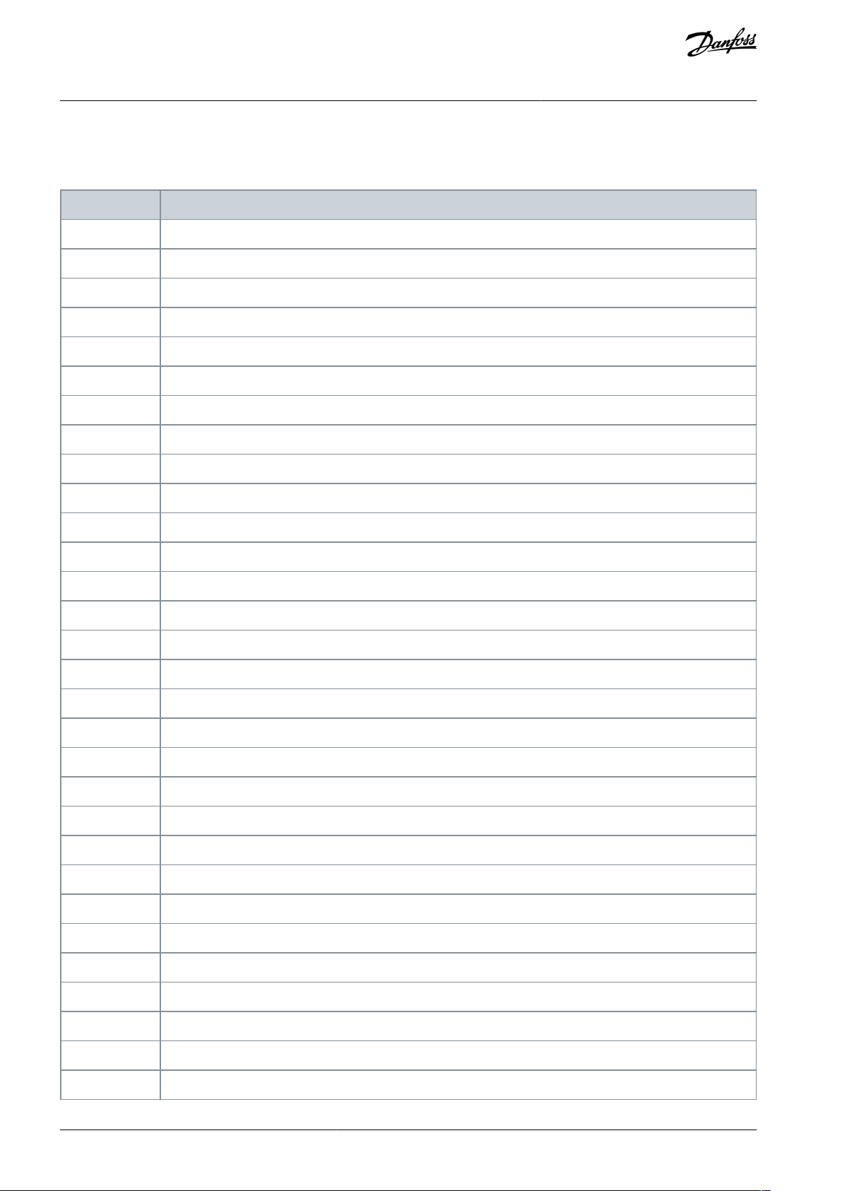
Code Description 120 SCR overtemperature 121 Battery/clock 122 Thermistor circuit 124 RTD/PT100 B 133 Overpower 134 Underpower 142 LCP disconnected 143 Zero speed detect 144 SCR Itsm 145 Instantaneous overcurrent 146 Rat…
8 Attributes
8.1 Trip Codes
Code
Description
0
No trip
11
Input A trip
20
Motor overload
21
Heatsink overtemperature
23
L1 phase loss
24
L2 phase loss
25
L3 phase loss
26
Current imbalance
27
Ground fault
28
Overcurrent
29
Undercurrent
50
Power loss
51
Undervoltage
52
Overvoltage
54
Phase sequence
55
Frequency
60
Incorrect control card
61
FLC out of range
62
EEPROM fail (parameter out of range)
75
Motor thermistor
101
Excess start time
102
Motor connection
104
Internal fault
110
Input B trip
113
Communications card fault
114
Network communication
115
L1-T1 shorted
116
L2-T2 shorted
117
L3-T3 shorted
119
Bypass overload
AN353423548483en-000201 / 130R094526 | Danfoss A/S © 2022.10
Attributes
EtherNet/IP Card
Installation Guide
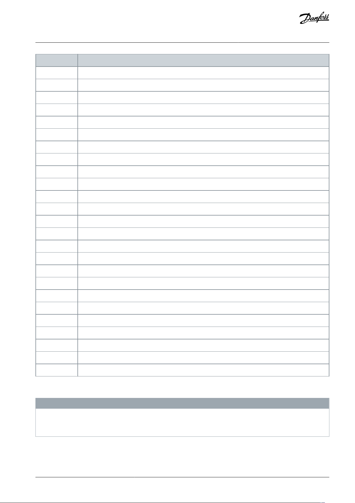
Code
Description
120
SCR overtemperature
121
Battery/clock
122
Thermistor circuit
124
RTD/PT100 B
133
Overpower
134
Underpower
142
LCP disconnected
143
Zero speed detect
144
SCR Itsm
145
Instantaneous overcurrent
146
Rating capacity
156
Current read error L1
157
Current read error L2
158
Current read error L3
160
Motor connection T1
161
Motor connection T2
162
Motor connection T3
163
Firing fail P1
164
Firing fail P2
165
Firing fail P3
166
VZC fail P1
167
VZC fail P2
168
VZC fail P3
169
Low control volts
170–182
Internal fault X. Contact the local supplier with the fault code (X).
8.2 Parameter Lists
N O T I C E
These parameter lists are for parameter list version 3.x. To check the parameter list version, read class 103d, instance 131, attrib-
ute 100.
For other parameter list versions, refer to the soft starter Operating Guide or contact the local supplier for assistance.
AN353423548483en-000201 / 130R0945 | 27Danfoss A/S © 2022.10
Attributes
EtherNet/IP Card
Installation Guide
N O T I C E
The numbering of parameter options via communications starts at 0. For Phase Sequence, 0 = Any sequence, 1 = Positive only, 2
= Negative only.
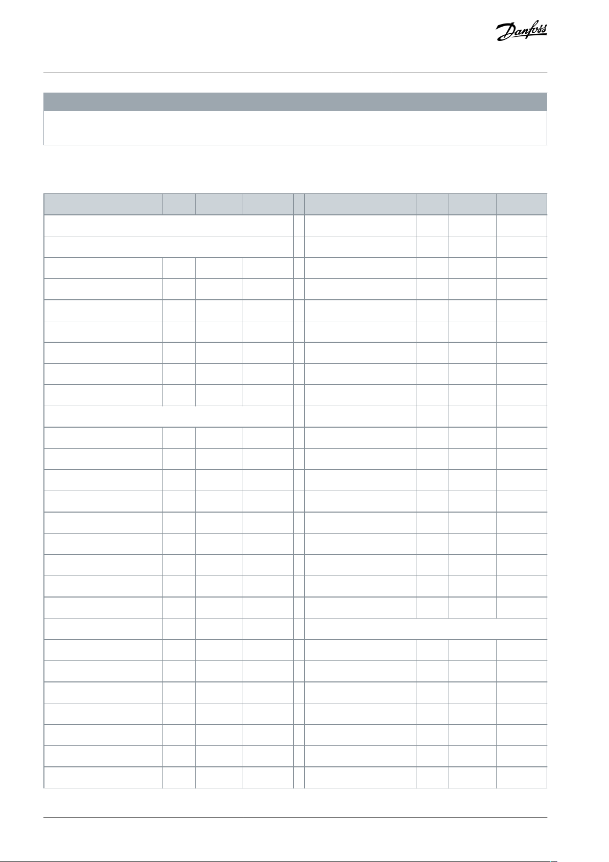
8.2.1 Parameters, Class 100, Class 101, and Class 102 Objects (Read/Write)
Table 9: Objects with Class, Instance, and Attribute (Read/Write)
Object name
Class
Instance
Attribute
Object name
Class
Instance
Attribute
Class 100 objects
Motor kW-2
100
127
100
Motor details
Start Mode-2
100
128
100
Command Source
100
101
100
Start Ramp Time-2
100
129
100
Motor Full Load Current
100
102
100
Initial Current-2
100
130
100
Motor kW
100
103
100
Current Limit-2
100
131
100
Locked Rotor Time
100
104
100
Adaptive Start Profile-2
100
132
100
Locked Rotor Current
100
105
100
Kickstart Time-2
100
133
100
Motor Service Factor
100
106
100
Kickstart Level-2
100
134
100
Reserved
100
107
100
Jog Torque-2
100
135
100
Motor start/stop
Stop Mode-2
100
136
100
Start Mode
100
108
100
Stop Time-2
100
137
100
Start Ramp Time
100
109
100
Adaptive Stop Profile-2
100
138
100
Initial Current
100
110
100
Adaptive Control Gain-2
100
139
100
Current Limit
100
111
100
Multi Pump-2
100
140
100
Adaptive Start Profile
100
112
100
Start Delay-2
100
141
100
Kickstart Time
100
113
100
DC Brake Torque-2
100
142
100
Kickstart Level
100
114
100
DC Brake Time-2
100
143
100
Jog Torque
100
115
100
Brake Current Limit-2
100
144
100
Stop Mode
100
116
100
Soft Brake Delay-2
100
145
100
Stop Time
100
117
100
Auto-start/stop
Adaptive Stop Profile
100
118
100
Auto-Start/Stop Mode
100
146
100
Adaptive Control Gain
100
119
100
Run Time
100
147
100
Multi Pump
100
120
100
Stopped Time
100
148
100
Start Delay
100
121
100
Sunday Mode
100
149
100
DC Brake Torque
100
122
100
Sunday Start Time
100
150
100
DC Brake Time
100
123
100
Sunday Stop Time
100
151
100
Brake Current Limit
100
124
100
Monday Mode
100
152
100
AN353423548483en-000201 / 130R094528 | Danfoss A/S © 2022.10
Attributes
EtherNet/IP Card
Installation Guide