OM-1352-003_w.pdf - 第30页
2-1 Tg1357-ID-SO 0703-003 2. Placement Action Mode 2.1 Normal Operation (Dip T ransfer 1) Transfer Position Component Picks with Nozzle #1 Multi Functional Head Component Recognition Camera Nozzle Stocker (Housing) (Step…
1-8
Tg1357-ID-SO
0703-003
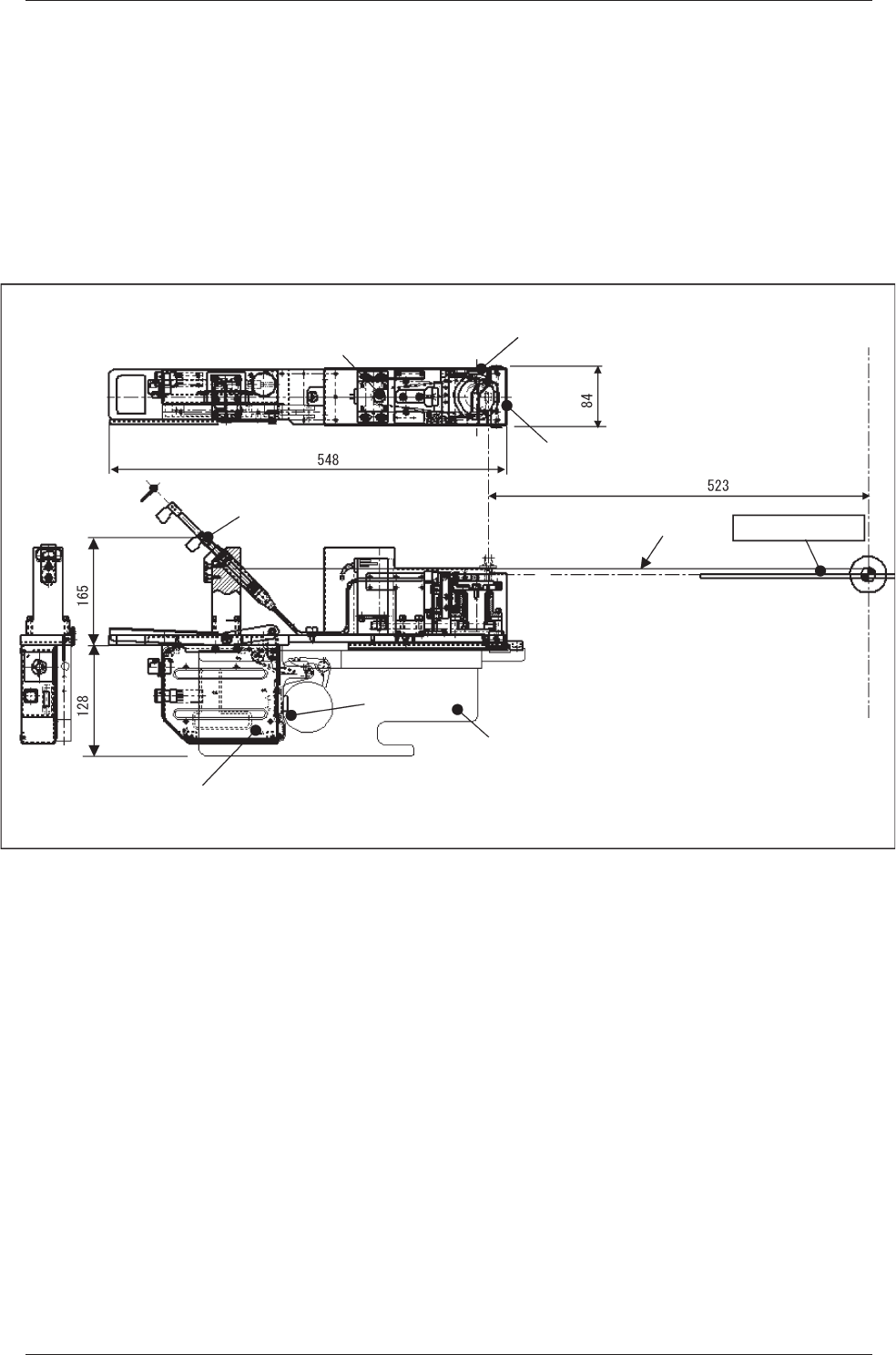
1.5 Outline of Actions
(1) Flux is deposited on the drum (rotational disk) and the thick film
is flattened evenly by the squeegee whose height is adjusted to the
specified one.
(2) The drum is stopped just before flux dispensing and flux transfer opera
-
tion is performed.
Squeegee
(For Even Flattening of Flux)
Rotational Disk
(Flux
Transfer Position)
Manual Supply Motor
(For
Table Rotation)
(Depth)
Syringe
(Flux is supplied automatically)
Feeder Control PCB
Feeder Base
Drawer
Connector
Pass Line
PCB Positioning Upper Surface
Center of
Machine
(Width)
(Push Out the Flux in the Syringe)
Fig.4
1.5 Outline of Actions
2-1
Tg1357-ID-SO
0703-003
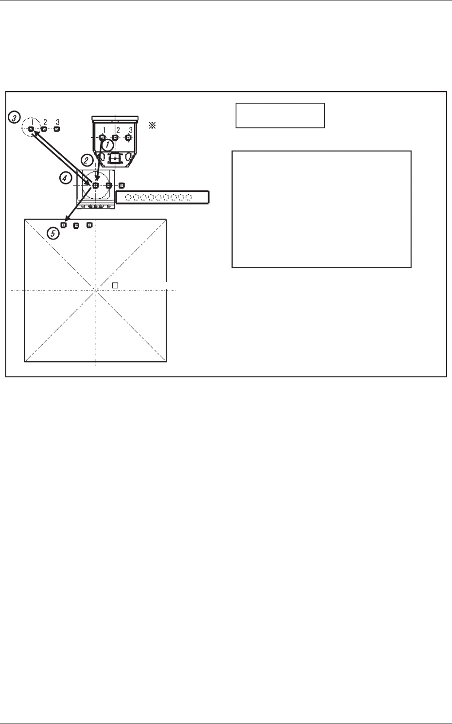
2. Placement Action Mode
2.1 Normal Operation (Dip Transfer 1)
Transfer Position
Component Picks
with Nozzle #1
Multi Functional Head
Component Recognition Camera
Nozzle Stocker (Housing)
(Step 1) Pickup → (Step 2) Recognition (Outline and
Bump) → (Step 3) Flux Application →
(Step 4) Recognition (Outline) → (Step 5) Placement
Note: When the component is placed (step 5) the
bump position is estimated, based on the
outline after correction in steps 2 and 4, and
the component is placed by using the bump as
the reference. For the XY placement position,
the component is placed using the PEC
recognition mark as the reference.
PCB (460 × 460)PCB (460 × 460)
<Dip Transfer 1>
Fig.5
2. Placement Action Mode
2-2
Tg1357-ID-SO
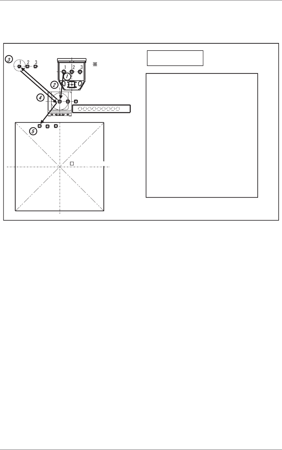
2.2 Bump Ball Missing Confirmation after Flux Dispensing
(Dip Transfer 2)
Transfer Position
Component Picks
with Nozzle #1
Multi Functional Head
Component Recognition Camera
Nozzle Stocker (Housing)
(Step 1) Pickup → (Step 2) Recognition (Bump) →
(Step 3) Flux Application →
(Step 4) Recognition (Bump) → (Step 5) Placement
Note: When the recognition is performed (step 4),
the bump missing check and flux application
check (if the flux is applied on the bump) are
performed.
For the XY placement position (where the
bump is limited to recognizable components,
after the flux application) the component is
placed by using the PEC recognition mark as
the reference.
The position is estimated and the component
placed using the bump as the reference.
PCB (460 × 460)PCB (460 × 460)
<Dip Transfer 2>
Fig.6
0703-003
2.2 Bump Ball Missing Confirmation after Flux Dispensing (Dip Transfer 2)