OM-1352-003_w.pdf - 第33页
2-4 Tg1357-ID-SO 2.3 Recognition of Bottom Component Land before Placement (Dip T ransfer 3) Transfer Position Component Picks with Nozzle #1 Multi Functional Head Component Recognition Camera Nozzle Stocker (Housing) &l…
2-3
Tg1357-ID-SO
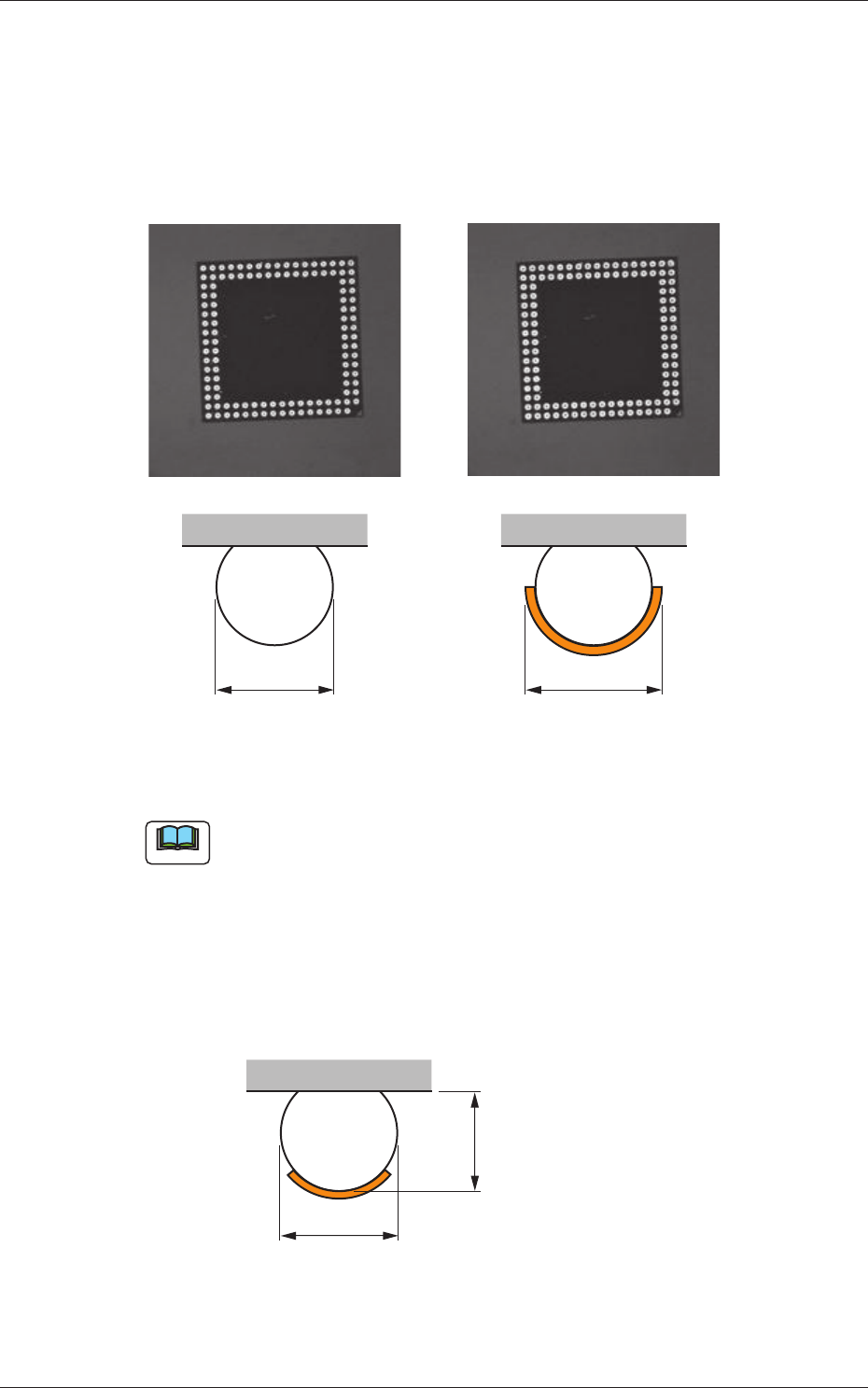
This function confirms that, certainly, the flux has been applied to all bumps
after the flux application.
When the flux has been applied, the bump diameter normally looks larger in
the recognition processing. By means of measuring the bump diameters and
comparing them before and after the flux application you are able to ensure
whether or not the flux has been judged.
D D +
a
Before Application After Application
Fig.7
Note
(a) This function is applicable to the bump diameter of
φ
0.4mm or more.
(b) If the flux coating thickness is too thin for the bump thickness, the
following figure shows the resultant difference as too small in the
measuring of bump diameter before and after the flux application.
If the flux coating thickness is too thick and the flux is attached to the
mold, the bump diameter can not be accurately measured.
This function should be used to secure a coating thickness of about
60% of bump thickness.
D
Before Application
Bump Thickness
Fig.8
0703-003
2.2 Bump Ball Missing Confirmation after Flux Dispensing (Dip Transfer 2)
2-4
Tg1357-ID-SO
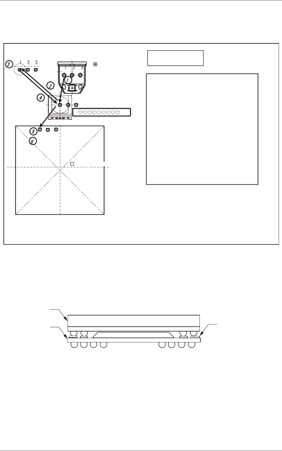
2.3 Recognition of Bottom Component Land before
Placement (Dip Transfer 3)
Transfer Position
Component Picks
with Nozzle #1
Multi Functional Head
Component Recognition Camera
Nozzle Stocker (Housing)
<Dip Transfer 1> + Recognition of Bottom
Component Land before Placement
(Step 1) Pickup → (Step 2) Recognition (Outline and
Bump) → (Step 3) Flux Application →
(Step 4) Recognition (Outline) →
(Step 5) Land Recognition → (Step 6) Placement
<Dip Transfer 2> + Recognition of Bottom
Component Land before Placement
(Step 1) Pickup → (Step 2) Recognition (Bump)
→ (Step 3) Flux Application →
(Step 4) Recognition (Bump) →
(Step 5) Land Recognition → (Step 6) Placement
PCB (460 × 460)PCB (460 × 460)
<Dip Transfer 3>
Fig.9
In the POP component placement, this function recognizes the land on the
upper surface of the bottom component, and finds the placement position for
the bottom component, and then places the top component.
Land on the upper
surface of
the bottom component
Top Component
Bottom
Component
Fig.10
0703-003
2.3 Recognition of Bottom Component Land before Placement (Dip Transfer 3)

3-1
Tg1357-ID-SO
0703-003
3. Handling of Flux Dispensing Unit
Notice
Before installing a flux dispensing unit on the bank feeder change
cart, note the following.
• Lock the caster brakes (2 places) of the bank feeder change cart.
• If the flux dispensing unit is seated afloat, vacuum nozzles or the
machine (GXH Series) will be damaged, causing pickup errors.
Be sure to install the flux dispensing unit correctly.
CAUTION
•
Be sure to hold the handle to move the bank feeder change cart.
•
While attaching the handle slides, be sure to prevent your
fingers from getting jammed.
•
Be careful not to hit your foot against the cart while moving the
bank feeder change cart.
•
Try to wear a pair of shoes that can protect your toes and have
slip- and puncture-resistance soles (thickness: 10 mm or more)
while working.
3. Handling of Flux Dispensing Unit