OM-1352-003_w.pdf - 第52页
6-3 Tg1357-ID-SO 0703-003 [2] [Unit #1] through [Unit #4] Buttons Select the flux dispensing unit to be used. When a flux dispensing unit is selected, the ID is displayed in the text box entitled "Component ID". …
6-2
Tg1357-ID-SO
0703-003
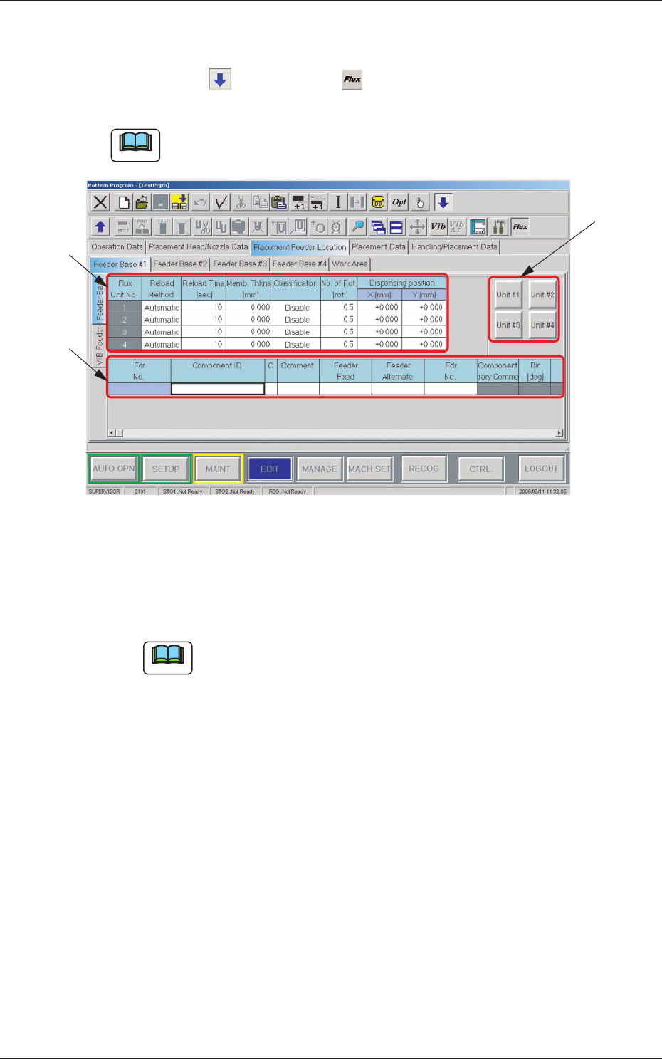
Open the "Feeder Base #1" tab sheet in the "Placement Feeder Location" tab
sheet.
Press the icon ( ) and then icon ( ) to open the "Feeder Base" tab
sheet and edit the "Feeder Base" data.
Note
As for Feeder Bases #2 and #3, follow the same procedure to open the cor-
responding tab sheets.
[3]
[2]
[1]
Fig. 19 "Feeder Base #1" Tab Sheet
[1] Flux Unit Nos. 1 to 4
Reload Method
Select the flux reload method from "Manual" and "Automatic".
Note
In this unit, select "Manual".
Reload Time [sec]
Set the flux reload time period.
Memb. Thkns [mm]
Set the coating thickness.
Classification
Set the flux type used in the flux dispensing unit.
No. of Rot. [rot.]
Specify the rotational speed of the drum (rotational disk).
Data Input Range: 0.5 to 5 [Rotations]
Dispensing Position X,Y[mm]
Set the dispensing position offset values.
6.1 Pattern Program
6-3
Tg1357-ID-SO
0703-003
[2] [Unit #1] through [Unit #4] Buttons
Select the flux dispensing unit to be used.
When a flux dispensing unit is selected, the ID is displayed in the text
box entitled "Component ID".
[3] List of Placement Feeder Location Data
Set the flux spreading unit to be installed on each feeder base.
Fdr No.
This indicates the feeder Nos. where flux dispensing units can be
arranged.
Note
Up to 5 feeder Nos. (Fdr Nos. equivalent to 5 lanes) can be used for
one feeder base.
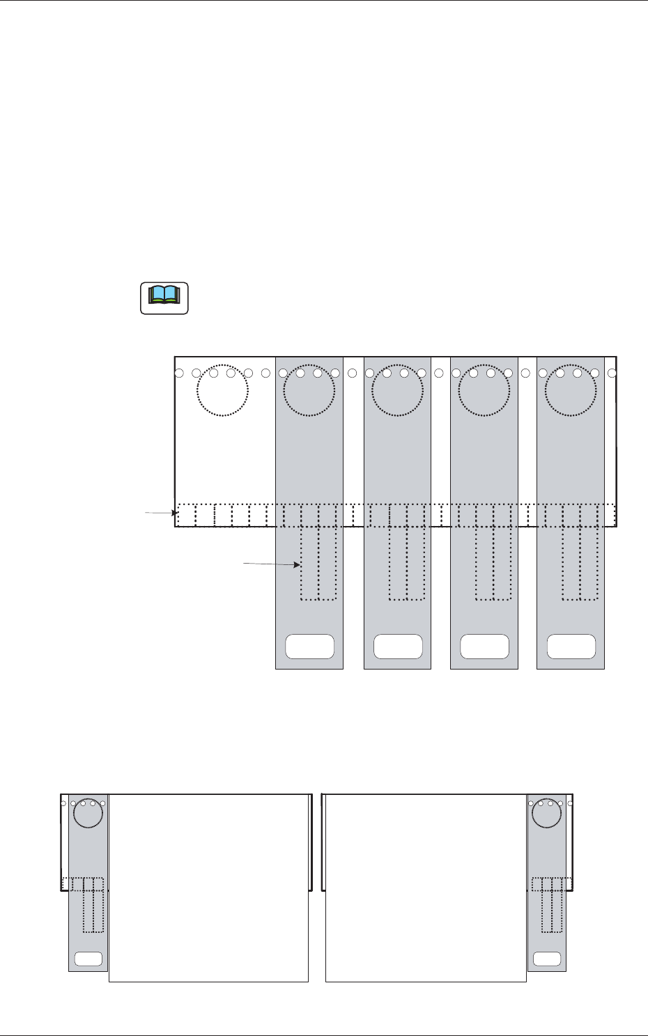
x01
x49
2 1
25 24 23 22 21 20 19 18 17 16 15 14 13 12 11 10 9 8 7 6 5 4 3 2 1
2 12 12 1
Connector on Feeder
Base Side
Connector on Flux Transfer
Device Side
Unit #4
<FLUX.UNIT #4>
Unit #3
<FLUX.UNIT #3>
Unit #2
<FLUX.UNIT #2>
Unit #1
<FLUX.UNIT #1>
Fig. 20 Example of One Feeder Base with Maximum Number of Flux Dispensing Units
2 1
4 3 2 1
x 49
25 24 23 22
2 1
For Blocks 1 and 4 For Blocks 2 and 3
Multi-Layer Tray Feeder
(JEDEC Size)
Multi-Layer Tray Feeder
(JEDEC Size)
Unit #1
Unit #1
x 01
Fig. 21 Multi-Layer Tray Feeder on Each Block
6.1 Pattern Program
6-4
Tg1357-ID-SO
0703-003
Component ID
Component IDs can be specified in each text box.
When one of the unit No. buttons ([Unit #1] through [Unit #4] buttons)
is selected, the corresponding dispensing unit No. is displayed like
"FLUX. UNIT #1" to "FLUX. UNIT #4".
C
Set a control command.
Notice
If a control command other than the following ones is used, the
step becomes invalid.
- (hyphen) :
This command handles the steps as those for the
placement feeder location data.
E : This command shows the end of the placement feeder
location data.
The step where "E" is set is valid.
S : This command invalidates the steps specified as
placement feeder location data.
X : This command invalidates the steps specified as
placement feeder location data and shows the end of
the data.
Comment
Set a comment for each Fdr No.
Up to 32 characters can be used.
Alphanumeric characters and symbols can be used.
Note
(a) The performance of the machine is not affected by these
commands. In other words, it has nothing to do with or without
these comments.
(b) It is recommended to set helpful information on components
related to the feeder Nos. (Fdr Nos.).
Feeder Fixed
Select "Enable" or "Disable" to determine whether or not the feeder
positions should be fixed in place.
When "Enable" is selected, the feeder Nos. (Fdr Nos.) and the
component IDs are not affected by any insert and delete operations of a
component.
Disable :
The feeder position is not fixed.
Enable : The feeder position is fixed.
6.1 Pattern Program