OM-1352-003_w.pdf - 第51页
6-2 Tg1357-ID-SO 0703-003 Open the "Feeder Base #1" tab sheet in the "Placement Feeder Location" tab sheet. Press the icon ( ) and then icon ( ) to open the "Feeder Base" tab sheet and edit …
6-1
Tg1357-ID-SO
0703-003
6. Data
6.1 Pattern Program
6.1.1 Placement Feeder Location Data
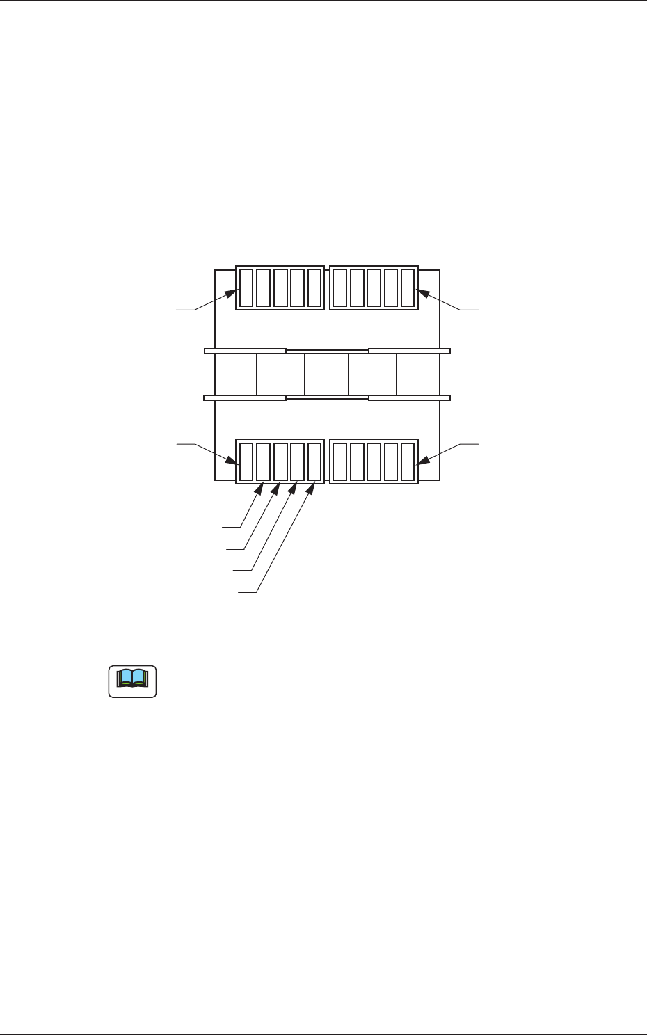
It must be specified on which feeder No. (Fdr. No.) of the feeder base the
flux dispensing unit should be installed.
Rear Side of Machine
Front Side of Machine
Feeder Base #3
Feeder Base #4
Feeder Base #2
Feeder Base #1
Unit #4
Unit #3
Unit #2
Unit #1
Fig. 18 Positional Relation between Feeder Bases and Flux Dispensing Units
Note
Up to 4 flux dispensing units can be installed on one feeder base.
6. Data
6-2
Tg1357-ID-SO
0703-003
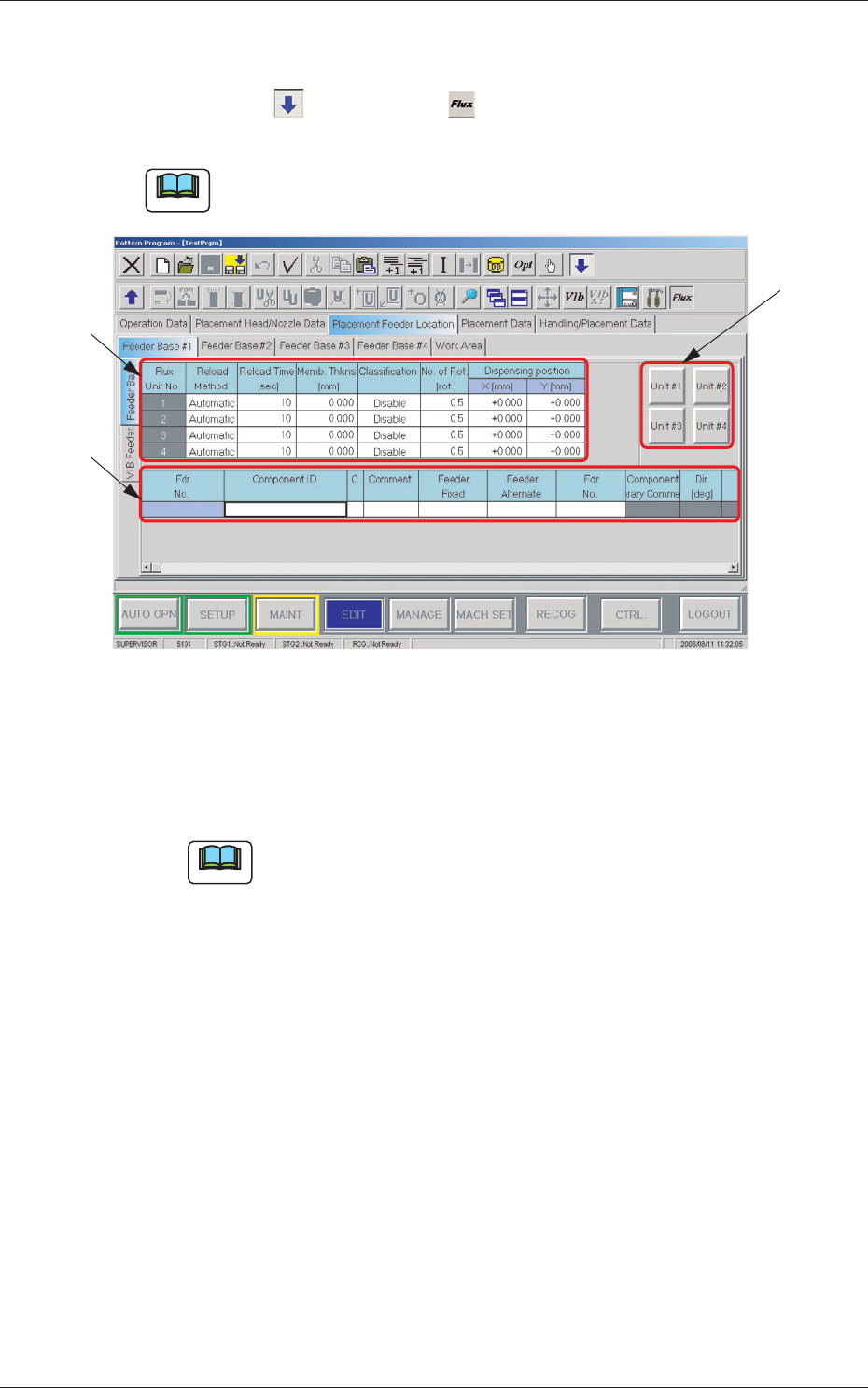
Open the "Feeder Base #1" tab sheet in the "Placement Feeder Location" tab
sheet.
Press the icon ( ) and then icon ( ) to open the "Feeder Base" tab
sheet and edit the "Feeder Base" data.
Note
As for Feeder Bases #2 and #3, follow the same procedure to open the cor-
responding tab sheets.
[3]
[2]
[1]
Fig. 19 "Feeder Base #1" Tab Sheet
[1] Flux Unit Nos. 1 to 4
Reload Method
Select the flux reload method from "Manual" and "Automatic".
Note
In this unit, select "Manual".
Reload Time [sec]
Set the flux reload time period.
Memb. Thkns [mm]
Set the coating thickness.
Classification
Set the flux type used in the flux dispensing unit.
No. of Rot. [rot.]
Specify the rotational speed of the drum (rotational disk).
Data Input Range: 0.5 to 5 [Rotations]
Dispensing Position X,Y[mm]
Set the dispensing position offset values.
6.1 Pattern Program
6-3
Tg1357-ID-SO
0703-003
[2] [Unit #1] through [Unit #4] Buttons
Select the flux dispensing unit to be used.
When a flux dispensing unit is selected, the ID is displayed in the text
box entitled "Component ID".
[3] List of Placement Feeder Location Data
Set the flux spreading unit to be installed on each feeder base.
Fdr No.
This indicates the feeder Nos. where flux dispensing units can be
arranged.
Note
Up to 5 feeder Nos. (Fdr Nos. equivalent to 5 lanes) can be used for
one feeder base.
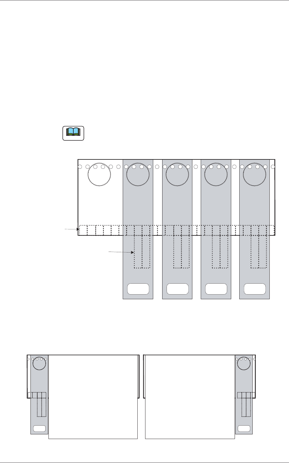
x01
x49
2 1
25 24 23 22 21 20 19 18 17 16 15 14 13 12 11 10 9 8 7 6 5 4 3 2 1
2 12 12 1
Connector on Feeder
Base Side
Connector on Flux Transfer
Device Side
Unit #4
<FLUX.UNIT #4>
Unit #3
<FLUX.UNIT #3>
Unit #2
<FLUX.UNIT #2>
Unit #1
<FLUX.UNIT #1>
Fig. 20 Example of One Feeder Base with Maximum Number of Flux Dispensing Units
2 1
4 3 2 1
x 49
25 24 23 22
2 1
For Blocks 1 and 4 For Blocks 2 and 3
Multi-Layer Tray Feeder
(JEDEC Size)
Multi-Layer Tray Feeder
(JEDEC Size)
Unit #1
Unit #1
x 01
Fig. 21 Multi-Layer Tray Feeder on Each Block
6.1 Pattern Program