OM-1352-003_w.pdf - 第59页
6-10 Tg1357-ID-SO Dispensing check Disable, Enable (100 %), Enable (80 %), Enable (60 %) Select whether the dispensing check function is enabled or not. Retention time [sec] Set the retention time at the bottom arrival p…
6-9
Tg1357-ID-SO
[2] Flux dispensing data
Operation mode
Operation mode settings.
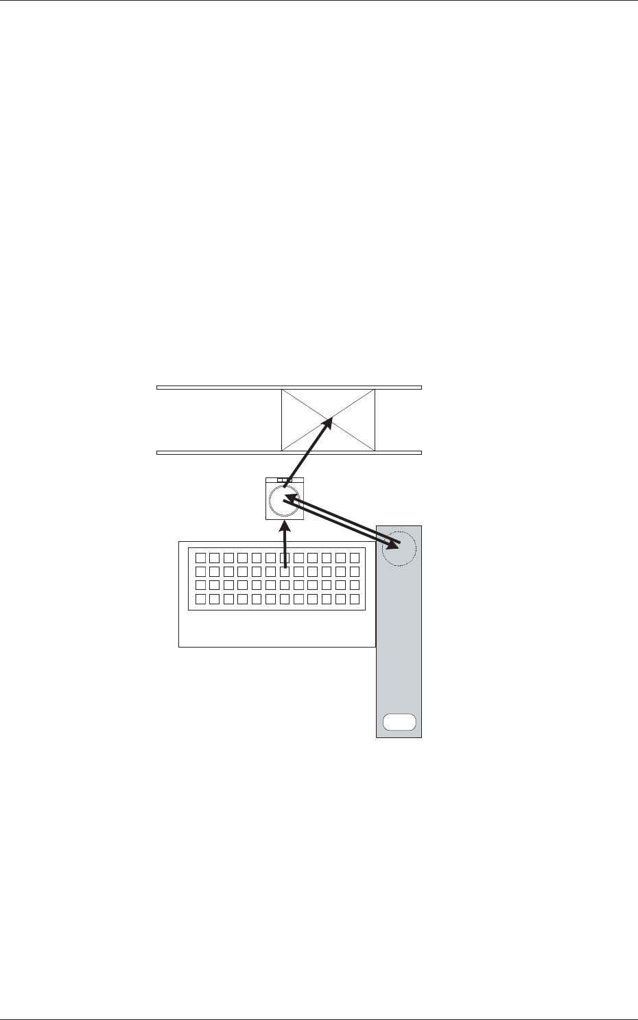
Outward Recog. : Ball + Outline → Flux application → Outline
Bump Recog. : Ball → Flux application → Ball
•
Outward Recog. mode
In the case that the bump can not be recognized after the flux
application, then this mode is used.
Perform the bump recognition and outline recognition before the flux
application, and again perform the outline recognition after the flux
application.
Based on the position relationship resultant from the outline recognition
before and after the flux application, calculate the bump position and
perform placement.
5. Placement
2. Component Recognition
(Bump, Outline)
4. Component Recognition (Outline)
1. Component Pick up
Multi-Layer Tray Feeder
3. Flux Application
Flux Dispensing Unit
Fig.26
•
Bump Recognition mode
In the case that the bump can be recognized even after the flux
application, then this mode is used.
Perform the bump recognition in each of "2. Component Recognition
(Bump, Outline)" and "4. Component Recognition (Outline)" steps.
0703-003
6.2 Component Library
6-10
Tg1357-ID-SO
Dispensing check
Disable, Enable (100 %), Enable (80 %), Enable (60 %)
Select whether the dispensing check function is enabled or not.
Retention time [sec]
Set the retention time at the bottom arrival point of the applied flux in
this text box.
•
Unit:
seconds
•
Data Input Range:
0.00 to 1.00 [second]
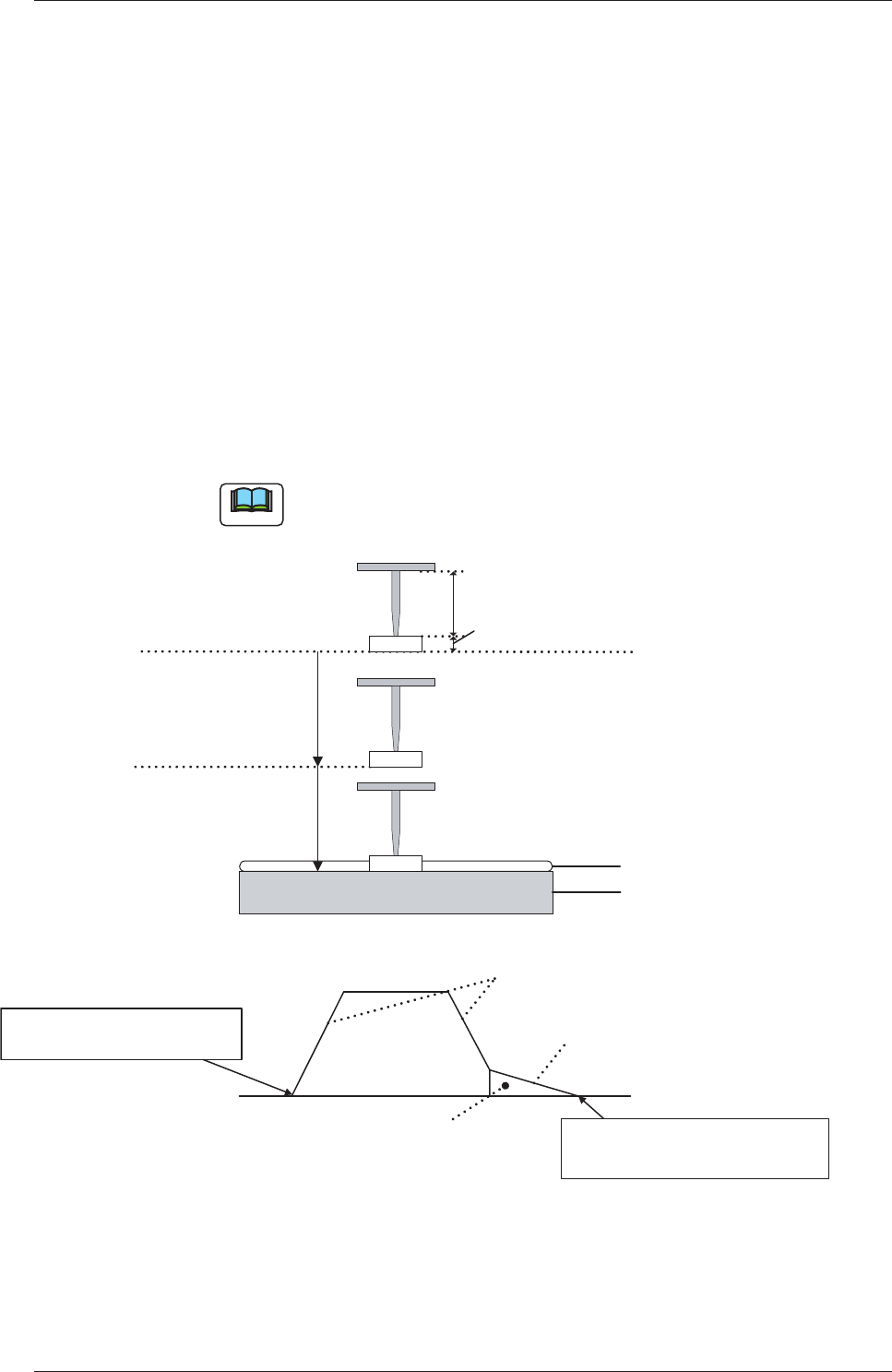
Descent dclr [%]
Enter a deceleration rate for the second L-axis descending stroke.
The figure below shows the L-axis control system related to the drum
surface on which flux is dispensed.
Note
"Placement Descent 1 [%]" is applied as a deceleration rate of the
first L-axis descending movement.
Nozzle Length
Component Thickness (t)
Placement Descent 1 [%]
Flux
Transfer Data
Descent Deceleration [%]
Starting Point of
L-Axis Descent Movement
Placement Decelerated Descent 1
Flux
Transfer Data
Descent Deceleration
Flux
Transfer Data
Descending Stroke Shift
Upper or Lower
Pass Line
Drum (Rotational disk)
L-Axis Positioning Completed
Drum Surface (Rotational disk)
Flux (Coating Pressure : 10
�m)
Fig. 27
0703-003
6.1 Pattern Program
6-11
Tg1357-ID-SO
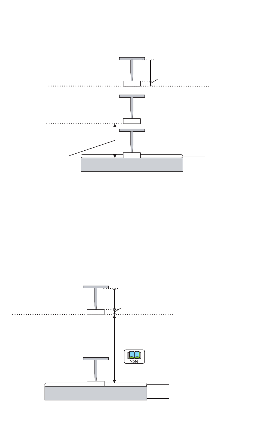
Descent dclr Stroke [mm]
The stroke distance for descent deceleration must be specified.
The figure below shows the L-axis control system related to the drum
(rotational disk) surface on which flux is dispensed.
Fig. 28
•
Data Input Range:
0.0 to 0.3 [mm]
Ascent dclr [%]
A deceleration rate of the L-axis ascent movement must be specified.
The figure below shows the L-axis control system related to the drum
(rotational disk) surface on which flux is dispensed.
Fig. 29
0703-003
6.1 Pattern Program
Nozzle Length
Component thickness (t)
Drum (Rotational disk)
Flux
Transfer Data
Ascent dclr [%]
Use the value of the pickup elevated deceleration
when the value of above-described is la
rger
than that of the pickup elevated deceleration.
Flux
(Coating Pressure : 10 �m)
Upper or Lower
Pass Line
Nozzle Length
Component Thickness (t)
Flux
Transfer Data
Descent Strok [mm]
Drum (Rotational disk)
Flux
(Coating Pressure : 10 �m)