OM-1352-003_w.pdf - 第49页
5-8 Tg1357-ID-SO 0703-003 [9] [Recog Dsp setup] Button When this button is pressed, the following window opens, enabling the operator to specify a graphic desplay mode for the recognized image, depending on whether the r…

5-7
Tg1357-ID-SO
0703-003
[4] "Result of Hysteresis Test" Group Box
Displayed are the results of a component recognition test.
[5] [ZERO]
Button
When pressed, this button zeroes all axes on the stage side where the
selected X/Y beam is located. For example, when Beam #1 or #2 is
selected, all axes on Stage #1 are zeroed. Selection of Beam #3 or #4
zeroes all axes Stage #2.
[6] [Save Image] Button
When this button is pressed, the "Save Image" window appears.
This button can also be used to save the test results.
[7] [Noz exchange] Button
When this button is pressed, the "Noz exchange" window appears.
[8] Camera Center
[Head] Button
This button is used to align the center of the camera with that of the
head.
[Comp.] Button
This button is used to align the componenet with the center of the
camera.
5.2 Component Recognition Test
5-8
Tg1357-ID-SO
0703-003
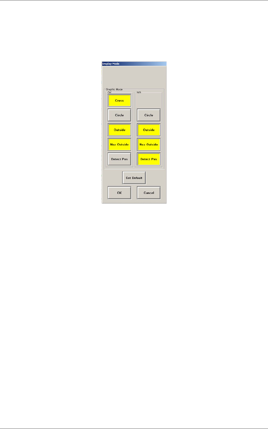
[9] [Recog Dsp setup] Button
When this button is pressed, the following window opens, enabling the
operator to specify a graphic desplay mode for the recognized image,
depending on whether the results of a recognition operation are normal
or abnormal.
Fig.17 "Display Mode" Window
[Cross] :
When this is selected and the results of a
recognition operation are normal, a cross-
hair appears at the center of the recognized
object.
[Circle] :
When this is selected, a circle appears on
the recognized object.
[Outside] :
When selected, this displays the outline of
the recognized object.
[Noz Outside] :
When selected, this displays the vacuum
nozzle that was used to recognize a
component.
[Detect Pos] :
When selected, this displays the detection
position and area.
[Set Default] :
When pressed, this button sets the defaults.
When several display types (multiple selection possible) are selected
and the [OK] button is pressed, the specified types (modes) are saved.
When the [Cancel] button is pressed, the selection is canceled.
5.2 Component Recognition Test
6-1
Tg1357-ID-SO
0703-003
6. Data
6.1 Pattern Program
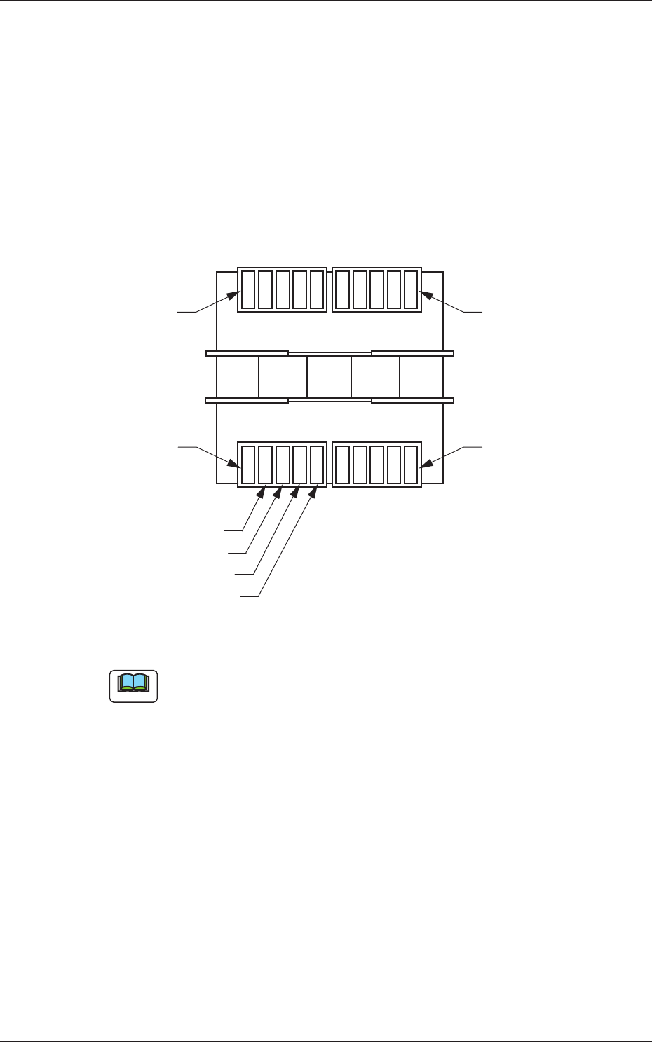
6.1.1 Placement Feeder Location Data
It must be specified on which feeder No. (Fdr. No.) of the feeder base the
flux dispensing unit should be installed.
Rear Side of Machine
Front Side of Machine
Feeder Base #3
Feeder Base #4
Feeder Base #2
Feeder Base #1
Unit #4
Unit #3
Unit #2
Unit #1
Fig. 18 Positional Relation between Feeder Bases and Flux Dispensing Units
Note
Up to 4 flux dispensing units can be installed on one feeder base.
6. Data