DeltaTherm_IR_REV_C.pdf - 第12页
DeltaTherm IR Cure Module Revision C / Sept ember 2022 Page 12 of 41 Operating Safety Notices and Warnin gs • 27B26B26B U se safet y glasses, glov es, and long-sleeved clothing. • 28B27B27B Rea d and understand al l oper…
DeltaTherm IR Cure Module
Revision C / September 2022
Page 11 of 41
Installation and Setup
269B268B268BWARNING: The following procedures should be done by qualified persons in
accordance with this manual and applicable safety regulations. A “qualified person”
is defined as “a person or persons who, by possession of a recognized degree or
certificate or professional training, or who, by extensive knowledge, training, and
experience, has successfully demonstrated the ability to solve problems relating to
the subject matter and work.” (ref. ANSI/ASME B30.2-1983.)
Installation
1. 24B23B23BPlug the machine into an appropriate power source as shown on the legend plate on
the module. The electrical service should be correctly grounded and the power
source “clean”. If high power equipment operates off the same source, a line
conditioner may be necessary. Poor quality power can cause errors in machine
operation.
270B269B269BWARNING: Failure to obey electrical specifications can cause damage to the machine
or injury to installation personnel. Electrical hookup must be done by a qualified
electrician and must obey any applicable local standards.
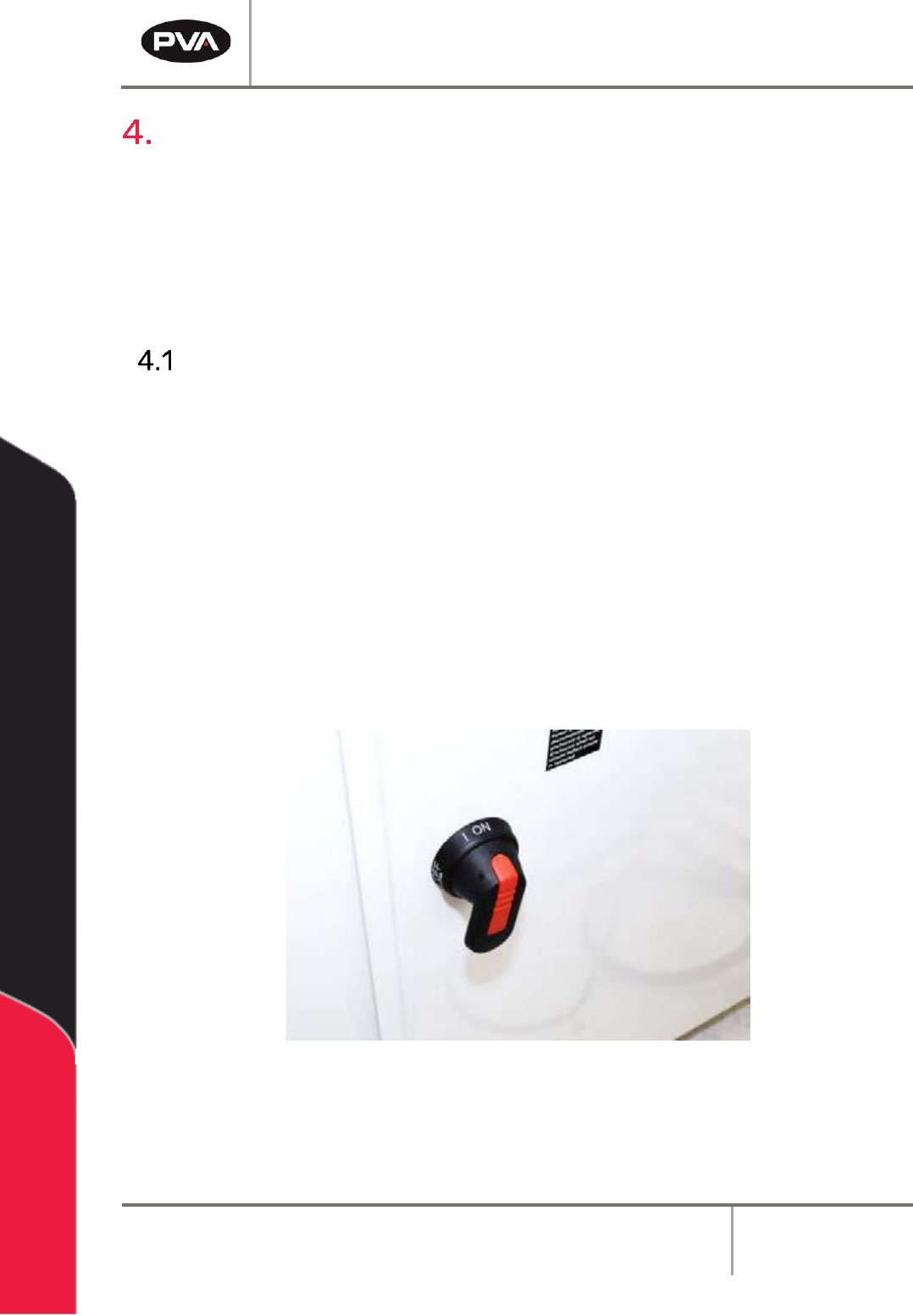
2. 25B24B24BClose any access doors and engage the EMERGENCY STOP button.
3. 26B25B25BTurn the main power switch to “On”.
190B189B189B
2B2B2BFigure 3: Power Switch "On"

DeltaTherm IR Cure Module
Revision C / September 2022
Page 12 of 41
Operating Safety
Notices and Warnings
• 27B26B26BUse safety glasses, gloves, and long-sleeved clothing.
• 28B27B27BRead and understand all operating manuals before you use this equipment.
• 29B28B28BDo not disable the safety features of the machine.
• 30B29B29BLock-out and tag the air and power supplies before you clean or service any part
of the system.
• 31B30B30BRelieve the pressure before you remove any hose.
• 32B31B31BDo not replace any hose with a hose of inadequate pressure rating.
• 33B32B32BUse only replacement parts recommended or supplied by the manufacturer.
• 34B33B33BStay away from all moving parts when the system is in operation.
Safety Devices and Guarding
191B190B190BThe DeltaTherm IR Cure Module has safety features that protect the operator from hazards
during normal operation of the machine.
271B270B270BNote: Do not bypass, disable, or tamper with the safety features. Precision Valve &
Automation, Inc. is not responsible for any damages incurred, mechanical or human,
because of changes or destruction of any safety features.
Safety Circuit
192B191B191BThe main power to the machine is monitored and controlled by the safety circuit. The
safety circuit has a control relay and one or more safety devices. The tripping contact of
the relay will disconnect power if the relay fails. Self-checking consists of positive guided
contacts which are mechanically forced to operate together. If the relay fails, the power
contact will open. The safety devices monitor the state of the EMERGENCY STOP button
and other safety mechanisms. When the safety relay detects that one or more of the safety
devices is open, the power to the motors and pneumatics is stopped.
Doors
193B192B192BAccess to the machine is provided by two doors. Modules have door protection through a
non-defeatable limit switch. The IR panels are disabled if a door is open.
DeltaTherm IR Cure Module
Revision C / September 2022
Page 13 of 41
Exhaust Requirements
Machine
Exhaust
Requirement
Machine Duct Size
Air Velocity at Test
Point (ft/min)
Air Velocity at
Test Point (m/sec)
DeltaTherm 4’
200 CFM
4” (102mm)
2292
11.6
DeltaTherm 8’
300 CFM
6” (152mm)
1528
7.8
DeltaTherm 8’ H
140 CFM
6” (152mm)
713
3.6
DeltaTherm 12’
600 CFM
6” (152mm)
3056
15.5
DeltaTherm 12’ H
210 CFM
6” (152mm)
1070
5.4
DeltaTherm 16’
1000 CFM
6” (152mm)
5093
25.9
DeltaTherm 16’ H
280 CFM
6” (152mm)
1426
7.2
194B193B193BNote: Check machine specifications. Custom order machines and processes may require
higher exhaust flow rates.
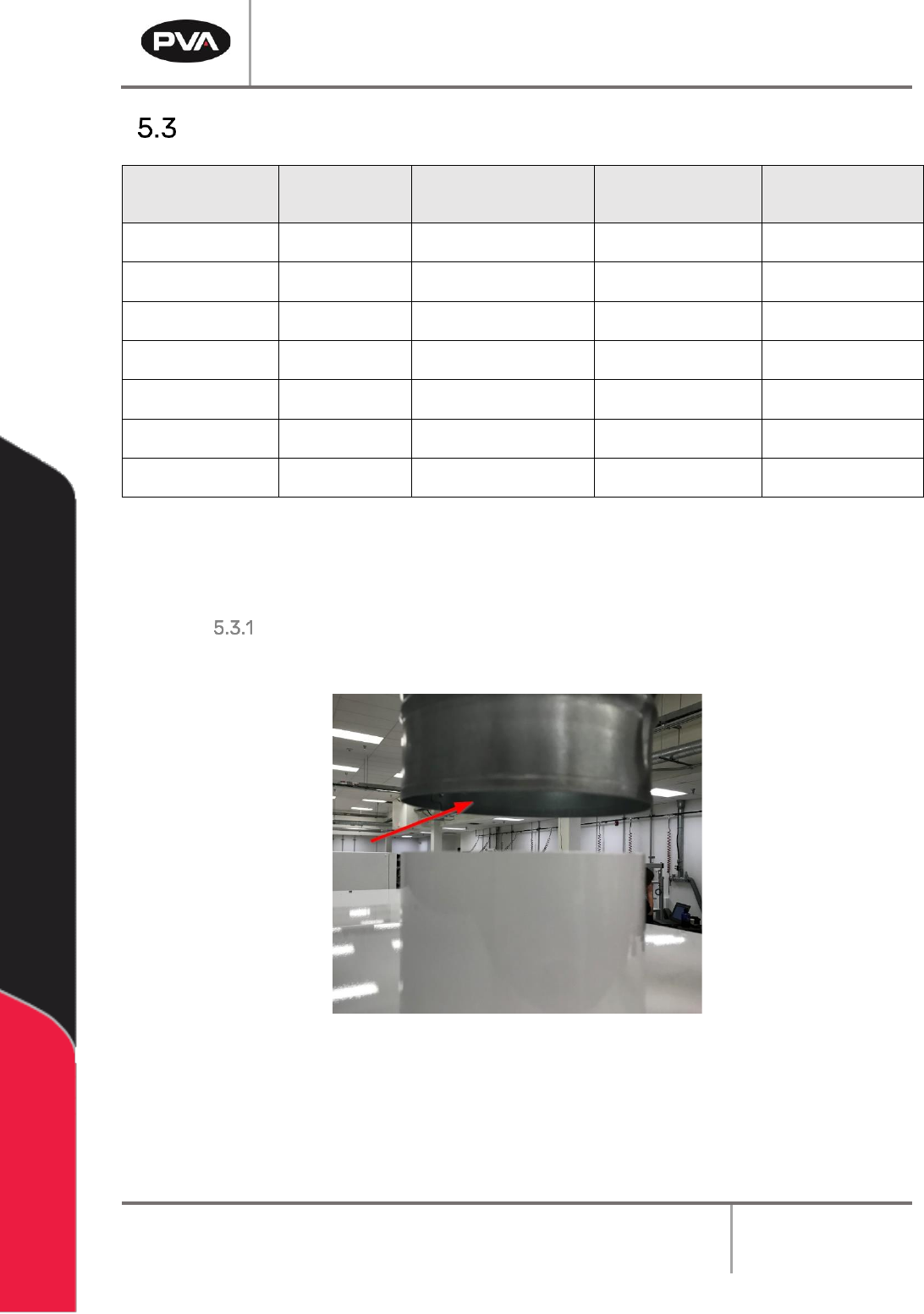
Air Velocity Test Point
195B194B194BMeasure the velocity at the inlet to the factory supplied duct.
196B195B195B
3B3B3BFigure 4: Air Velocity Test Point