DeltaTherm_IR_REV_C.pdf - 第14页
DeltaTherm IR Cure Module Revision C / Sept ember 2022 Page 14 of 41 Operat ion 272B271B271B Note: The scre ens shown in this manua l are exampl es. However, t he terminolog y used on the scr eens is consist ent for all …
DeltaTherm IR Cure Module
Revision C / September 2022
Page 13 of 41
Exhaust Requirements
Machine
Exhaust
Requirement
Machine Duct Size
Air Velocity at Test
Point (ft/min)
Air Velocity at
Test Point (m/sec)
DeltaTherm 4’
200 CFM
4” (102mm)
2292
11.6
DeltaTherm 8’
300 CFM
6” (152mm)
1528
7.8
DeltaTherm 8’ H
140 CFM
6” (152mm)
713
3.6
DeltaTherm 12’
600 CFM
6” (152mm)
3056
15.5
DeltaTherm 12’ H
210 CFM
6” (152mm)
1070
5.4
DeltaTherm 16’
1000 CFM
6” (152mm)
5093
25.9
DeltaTherm 16’ H
280 CFM
6” (152mm)
1426
7.2
194B193B193BNote: Check machine specifications. Custom order machines and processes may require
higher exhaust flow rates.
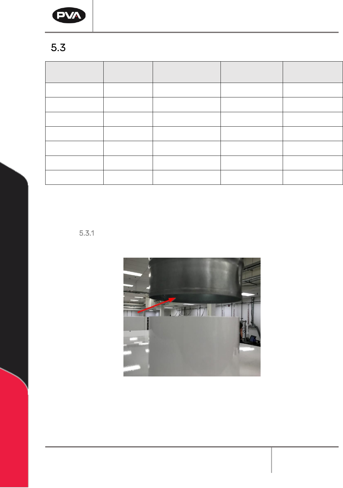
Air Velocity Test Point
195B194B194BMeasure the velocity at the inlet to the factory supplied duct.
196B195B195B
3B3B3BFigure 4: Air Velocity Test Point
DeltaTherm IR Cure Module
Revision C / September 2022
Page 14 of 41
Operation
272B271B271BNote: The screens shown in this manual are examples. However, the terminology
used on the screens is consistent for all machines. ON/OFF options are displayed by
showing black background with white lettering for ON and white background with
black lettering for OFF.
Startup Procedure
1. 35B34B34BClose all doors.
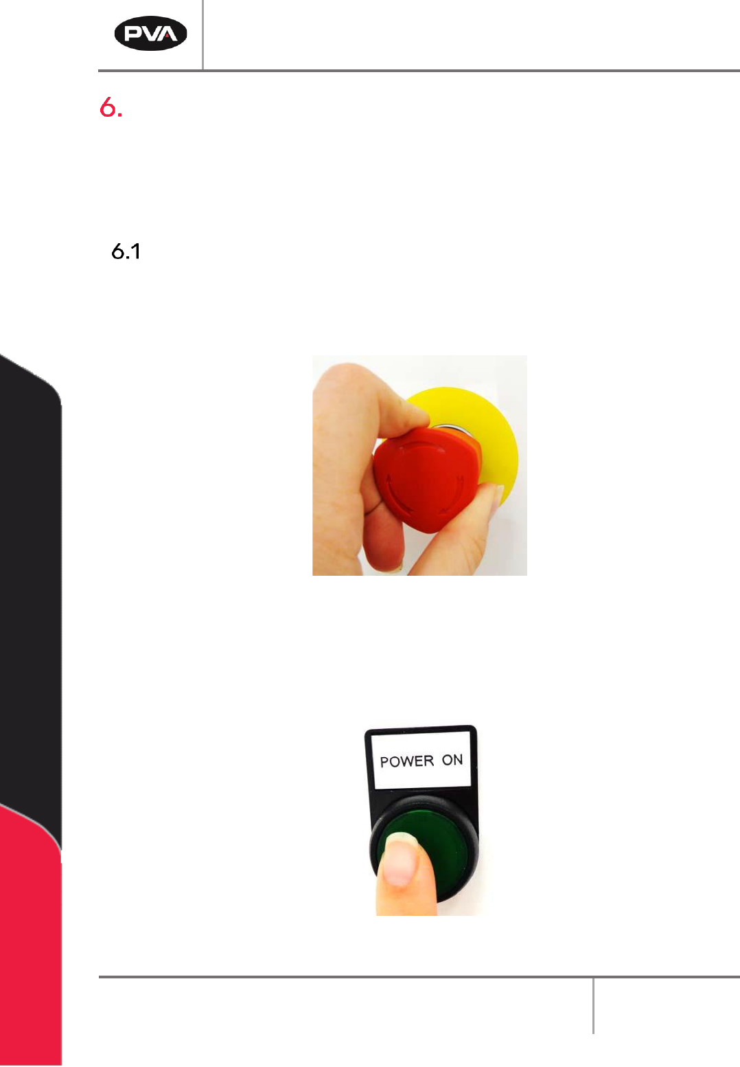
2. 36B35B35BEngage the EMERGENCY STOP button.
197B196B196B
4B4B4BFigure 5: Emergency Stop Button
3. 37B36B36BTurn the main power switch to ON.
4. 38B37B37BPush the green POWER ON button on the front of the DeltaTherm module.
198B197B197B
5B5B5BFigure 6: Power On Button
DeltaTherm IR Cure Module
Revision C / September 2022
Page 15 of 41
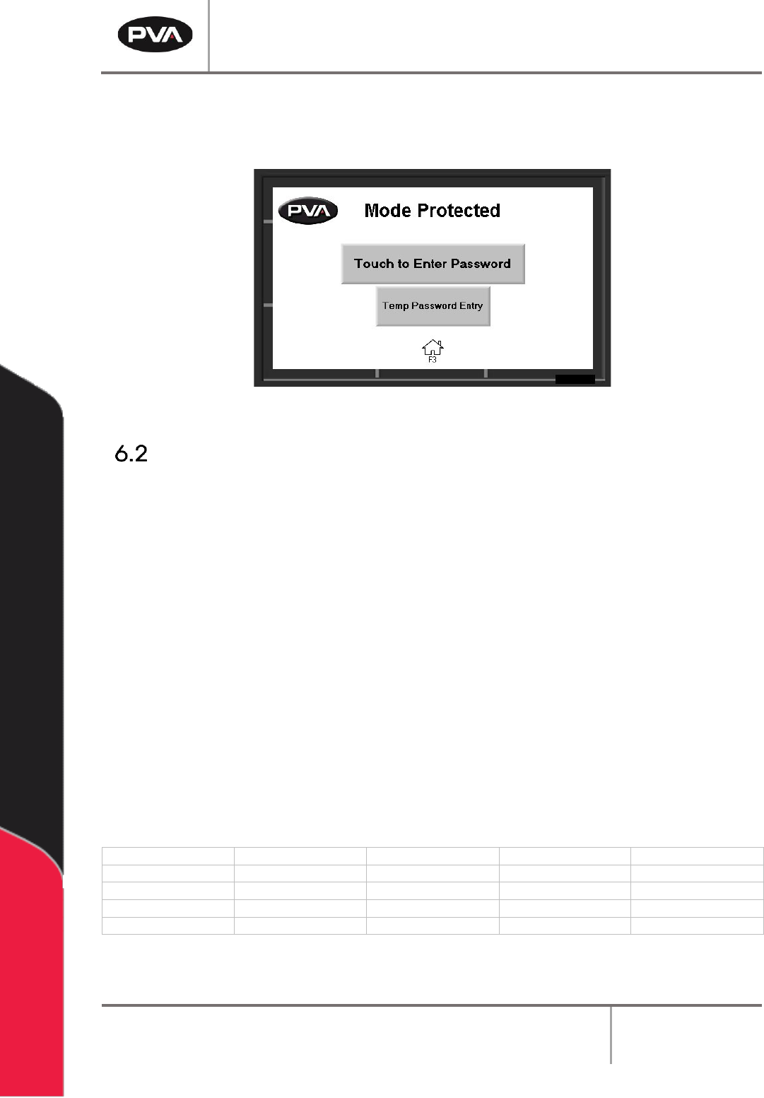
5. 39B38B38BEnter your password as necessary, if in protected mode.
6. 40B39B39BOperate the system as necessary.
199B198B198B
6B6B6BFigure 7: Enter Password
Light Tower Operation
200B199B199BThree stacked indicator lights and a buzzer are used to show the machine status. The
lights are green, amber, and red. The buzzer is below the green light. The lights are visible
from all sides of the machine. The indicators operate as follows:
• 41B40B40BThe green light is on when the machine is in Auto Cycle and operates within
specified parameters. It is off at all other times.
• 42B41B41BThe amber light is on when the machine is in Auto Cycle but the specified
parameters have not been reached. It is off at all other times.
• 43B42B42BThe red light is on steady when the machine is not in Auto Cycle due to operator
intervention. It flashes when the machine is in cycle, but the cycle is stopped
because of a machine problem. It is off at all other times.
• 44B43B43BThe buzzer cycles when the red light flashes with machine errors. It also cycles
briefly when a board is at the end of the machine and must be unloaded (if the
offload alert option is selected in the Setup mode).
State
Red
Amber
Green
Buzzer
Cycle Stop
ON
OFF
OFF
OFF
Auto Cycle
OFF
ON
OFF
OFF
In Cycle
OFF
OFF
ON
OFF
Machine Error
FLASH
OFF
OFF
FLASH
7B7B7BFigure 8: Light Tower & Buzzer Status