1_SME_DB_Feeder_User_Guide(Eng_Ver1.4).pdf - 第24页
1-6 SM-Series SME DB Tape Feeder User's Manual Figure1.5 SME 12~88mm tape feeder 1: T ape 2: T ape gui de 3: Frame 4: P art The Z value of the pi ckup poi nt i s applied in various ways acco rding to the feeder type…
1-5
Overview
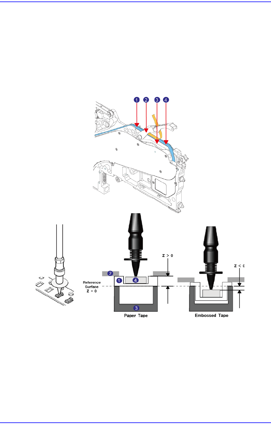
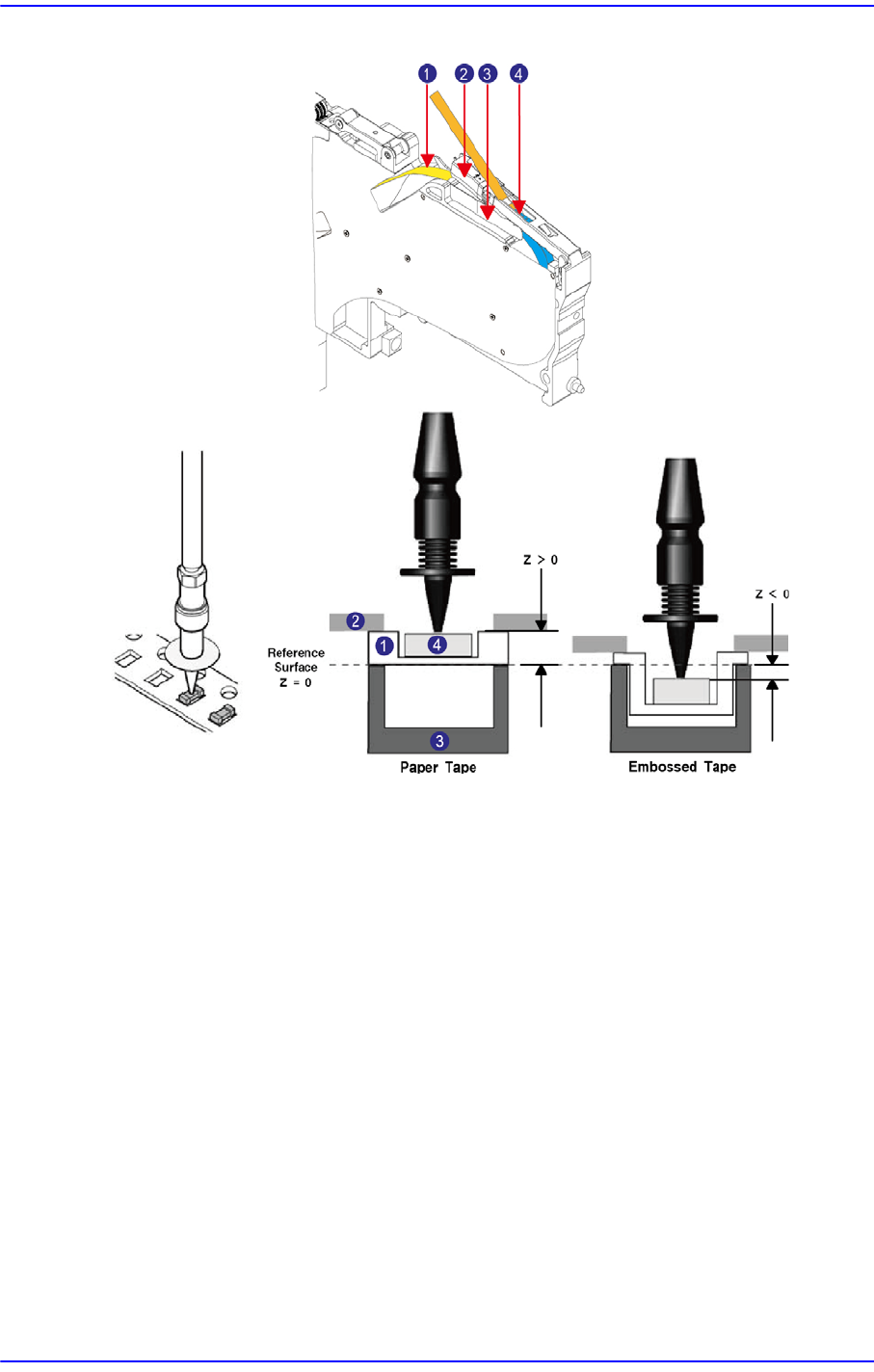
1.3. Reference for feeder’s pickup height setup
The reference plane for Z-axis height of the tape feeder is beneath (above the main frame)
the tape at the pickup position.
Actual pickup height of each part may vary depending on part height and transfer tape
thickness as shown in the following figure. In particular, embossed tape must be set
according to the actual part height against the pocket depth. It may become a negative (-)
value as shown in the following figure.
Figure1.4 SME 8mm / W4P1 tape feeder
1: Tape
2: Tape guide
3: Frame
4: Part
1-6
SM-Series SME DB Tape Feeder User's Manual
Figure1.5 SME 12~88mm tape feeder
1: Tape
2: Tape guide
3: Frame
4: Part
The Z value of the pickup point is applied in various ways according to the feeder type. In
addition, the Z value of the pickup point also varies according to the type of the part
supply tape. The embossed tape must be set according to the pocket depth and part height.
Sometimes, the pickup Z value is indicated as a negative (-) value.
1-7
Overview
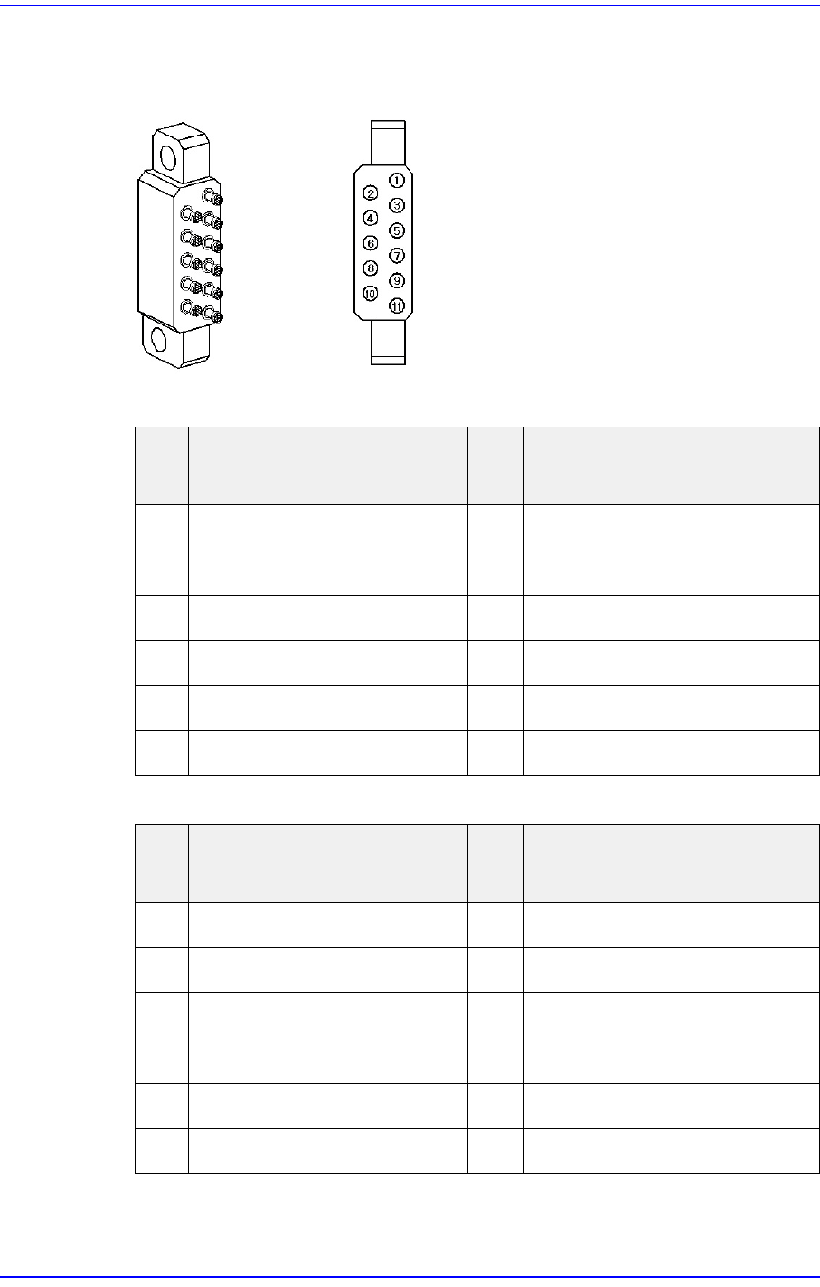
1.4. Probe Pin Components
Figure1.6 Probe Pin Layout
Table1.2 Probe Pin Assignment (Non IT)
Table1.3 Probe Pin Assignment (IT)
Pin
No.
Function Use
Pin
No.
Function Use
1 ID0 X 7 Indexing Signal
○
2 ID1 X 8 Clamping Signal
○
3 D24V X 9 Indexing Command
○
4 Communication X 10 F24V
○
5 Communication X 11 F24G
○
6 D24G X
Pin
No.
Function Use
Pin
No.
Function Use
1ID0
○
7 Indexing Signal
○
2ID1
○
8 Clamping Signal
○
3 D24V
○
9 Indexing Command
○
4 Communication
○
10 F24V
○
5 Communication
○
11 F24G
○
6 D24G
○