CP643规格书.pdf - 第12页
– 9 – CP-643E/643ME Specifications Edition 3.0 5. Nozzles 5.1 Nozzle T ypes and Nozzle Assembly (1) Each placing head carries up to 6 nozzles, selected from a range of 16 nozzle types. (2) Refer to the following table fo…
CP-643E/643ME Specifications
Edition 3.0
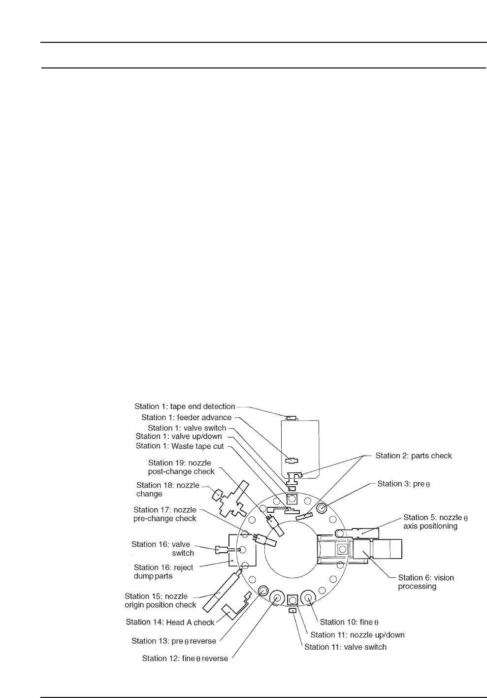
4. Twenty-head Turret
Station Function
1 Pick up part from the device table
2 Part detection (large parts only)
3Pθ: Parts prerotation to either 0°, +90° or -90°
4 Idle
5 Placing head clutch alignment
6 Vision processing
7 Idle
8 Idle
9 Idle
10 Fθ: Fine placement angle rotation (including adjustment)
11 Placement
12 FRθ: Fθ reverse rotation
13 PRθ: Pθ reverse rotation
14 A-head detection
15 Nozzle clutch origin detection
16 Reject parts discarded
17 Detection of nozzle type No. 1 - No. 6
18 Nozzle change
19 Nozzle change check (detect nozzle type No. 1 - 6)
20 Idle
– 8 –
– 9 – CP-643E/643ME Specifications
Edition 3.0
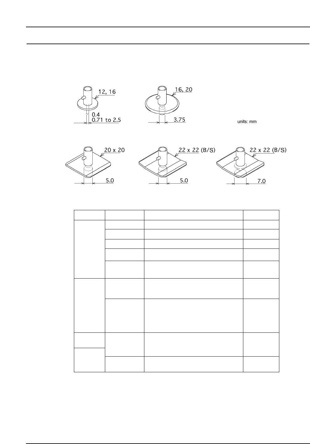
5. Nozzles
5.1 Nozzle Types and Nozzle Assembly
(1) Each placing head carries up to 6 nozzles, selected from a range of 16 nozzle types.
(2) Refer to the following table for nozzle types and applicable parts.
Notes: The letter in "Nozzle name" denotes the shape of the disk (except M).
R : Round (backlight) M : Round special nozzle for Melf (backlight)
S : Square (backlight) B : Square (frontlight)
Depending on the shape and weight of the part, a different nozzle may be required.
Both nozzles for backlighting and frontlighting can be used for placing CSPs.
1005 (in. 0402), 1608, (in. 0603) SSMIN
0603 (in. 0201), 1005 (in. 0402)
1608 (in. 0603), 2125, SMIN
2125, 3216, MIN, Tantalum A, Melf
3216, 3225, 4532, Tantalum A/B,
PTRR, Trimmer potentiometer
Tantalum B/C/D, PTRR, Melf,
SOIC 8, SSOP 16–20, Filter, CSP
SOIC 20–28W, SSOP 24–30, PLCC 18–32,
SQFP 48, SOJ26, QFP48, CSP
0.7
0.4
1.0
1.3
1.8
2.5
5.0
3.7
12
20
Disk size Nozzle diameter
Applicable parts
Trimmer potentiometer,
Aluminum electrolytic capacitor,
Tantalum D, SOIC 20–28W, SSOP 16–30,
PLCC 18–28, SQFP 48, SOJ 26, CSP
20 x 20 mm
Nozzle name
16
22 x 22 mm
22 x 22 mm
( black )
7.0
SOIC 20–28W, SOJ 26, PLCC 20-52, CSP
R12-007
R12-004
R12-010
M12-013
R12-018
R20-025
M20-025
R16-037
R20-037
S20-050
S22-050
B22-050
S22-070
B22-070
R12-013
R16-025
Units: mm
– 10 –
CP-643E/643ME Specifications
Edition 3.0
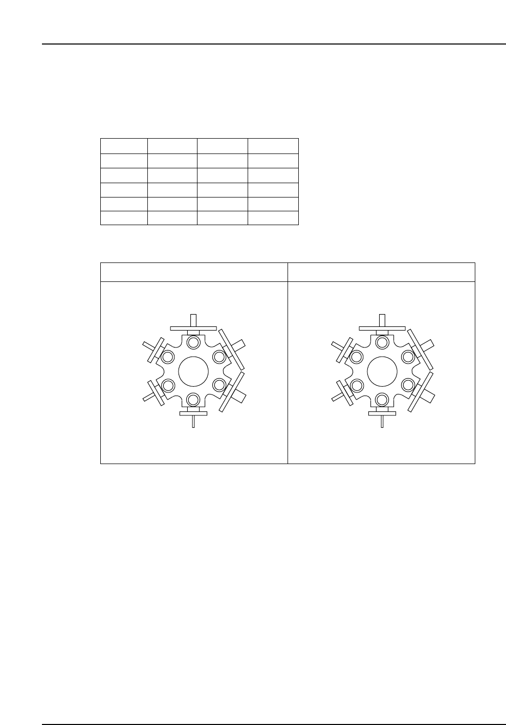
5.2 Nozzle Arrangement
The standard arrangement of nozzles is either type A or B, as shown in the illustration
below. Other arrangements can be selected from the table below.
Notes: Only a nozzle with a disk diameter of 20 mm or smaller can be positioned next to a
nozzle with a disk size of 20 x 20 mm.
Only a nozzle with a disk diameter of 16 mm or smaller can be positioned next to a
nozzle with a disk size of 22 x 22 mm (or 22 x 22 mm black).
Nozzles with a diameter of 0.4 mm must be positioned at any position other than
position 1 (recommended position: 6).
1
2
3
4
5
6
R12-007
R12-010
R12-013
R20-025
R20-037
S20-050
1
2
3
4
5
6
R12-010
R12-013
R12-018
R20-025
R20-037
S20-050
Type A
Nozzle Types
Type B
R12-004
R12-007
R12-010
R12-013
M12-013
R12-018
R16-025
R16-037
R20-025
M20-025
R20-037
S20-050
S22-050
B22-050
S22-070
B22-070