CP643规格书.pdf - 第13页
– 10 – CP-643E/643ME Specifications Edition 3.0 5.2 Nozzle Arrangement The standard arrangement of nozzles is either type A or B, as shown in the illustration below. Other arrangements can be selected from the table belo…
– 9 – CP-643E/643ME Specifications
Edition 3.0
5. Nozzles
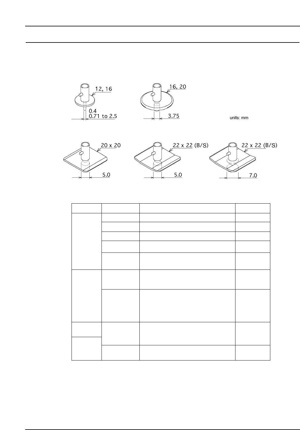
5.1 Nozzle Types and Nozzle Assembly
(1) Each placing head carries up to 6 nozzles, selected from a range of 16 nozzle types.
(2) Refer to the following table for nozzle types and applicable parts.
Notes: The letter in "Nozzle name" denotes the shape of the disk (except M).
R : Round (backlight) M : Round special nozzle for Melf (backlight)
S : Square (backlight) B : Square (frontlight)
Depending on the shape and weight of the part, a different nozzle may be required.
Both nozzles for backlighting and frontlighting can be used for placing CSPs.
1005 (in. 0402), 1608, (in. 0603) SSMIN
0603 (in. 0201), 1005 (in. 0402)
1608 (in. 0603), 2125, SMIN
2125, 3216, MIN, Tantalum A, Melf
3216, 3225, 4532, Tantalum A/B,
PTRR, Trimmer potentiometer
Tantalum B/C/D, PTRR, Melf,
SOIC 8, SSOP 16–20, Filter, CSP
SOIC 20–28W, SSOP 24–30, PLCC 18–32,
SQFP 48, SOJ26, QFP48, CSP
0.7
0.4
1.0
1.3
1.8
2.5
5.0
3.7
12
20
Disk size Nozzle diameter
Applicable parts
Trimmer potentiometer,
Aluminum electrolytic capacitor,
Tantalum D, SOIC 20–28W, SSOP 16–30,
PLCC 18–28, SQFP 48, SOJ 26, CSP
20 x 20 mm
Nozzle name
16
22 x 22 mm
22 x 22 mm
( black )
7.0
SOIC 20–28W, SOJ 26, PLCC 20-52, CSP
R12-007
R12-004
R12-010
M12-013
R12-018
R20-025
M20-025
R16-037
R20-037
S20-050
S22-050
B22-050
S22-070
B22-070
R12-013
R16-025
Units: mm
– 10 –
CP-643E/643ME Specifications
Edition 3.0
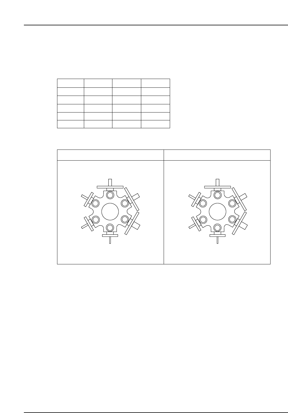
5.2 Nozzle Arrangement
The standard arrangement of nozzles is either type A or B, as shown in the illustration
below. Other arrangements can be selected from the table below.
Notes: Only a nozzle with a disk diameter of 20 mm or smaller can be positioned next to a
nozzle with a disk size of 20 x 20 mm.
Only a nozzle with a disk diameter of 16 mm or smaller can be positioned next to a
nozzle with a disk size of 22 x 22 mm (or 22 x 22 mm black).
Nozzles with a diameter of 0.4 mm must be positioned at any position other than
position 1 (recommended position: 6).
1
2
3
4
5
6
R12-007
R12-010
R12-013
R20-025
R20-037
S20-050
1
2
3
4
5
6
R12-010
R12-013
R12-018
R20-025
R20-037
S20-050
Type A
Nozzle Types
Type B
R12-004
R12-007
R12-010
R12-013
M12-013
R12-018
R16-025
R16-037
R20-025
M20-025
R20-037
S20-050
S22-050
B22-050
S22-070
B22-070
6. Parts Supply System
6.1 Parts Supply Table (D-axis)
(1) Types of parts CP-643E: 140 types (using two tables each loaded
with seventy 8 mm feeders)
CP-643ME: 100 types (using two tables each loaded
with fifty 8 mm feeders)
(2) Mountable parts Parts that comply with the packaging, feed pitch and
part height requirements as outlined in section 3.1,
“Performance Specifications”.
(3) Table drive method 2 motor/2 independent drive mechanisms
(4) Device table operating modes Select from the following 3 modes:
• Device Change Mode
• Changeover Mode
• Joint Mode
Note: As the two D-axis tables are controlled independently on this machine, both tables
cannot be completely joined when the machine is operated in the joint mode. Due to the
safety gap of approximately 150 mm between the two tables, there will be a delay of
approximately 0.5 seconds when the machine switches from Device #70 to Device #71
(CP643ME: #50 to #51).
(5) Feeder Pitch
Note: The terms "left side" and "right side" refer to the feeder
mounting positions when viewed from the rear of the machine.
(6) Feeder Types (which can be placed at the ends of the device tables)
W8 W12 W16 W24 W36
Machine Type
✕
✕
✕
✕
CP-643E
D1
D70
D71
D140
CP-643ME
D1
D50
D51
D100
✓
✕
✕
✕
✕
✕
✕
✕
✕
✕
✕
✕
✕
✓
✓
✓
W8
W12
W16
W24
W32
W8
1P
2P
2P
2P
2P
W12
2P
2P
2P
2P
3P
W16
2P
2P
2P
2P
3P
W24
2P
2P
2P
3P
3P
W32
2P
3P
3P
3P
3P
Left side
Right side
– 11 –
CP-643E/643ME Specifications
Edition 3.0