卧式standard头部.pdf - 第25页
Page 23 V/S Standard Insertion Head Assembly T50090901 Rev . F This Document Supports Assembly 50090901 Rev. D Procedures and Adjustments Inser tion Head Span Axis Adjustment Purpose: This procedure ensures that the inse…
Page 22
T50090901 Rev. F V/S Standard Insertion Head Assembly
This Document Supports Assembly 50090901 Rev. D
Functional Description
The insertion head assembly contains the tooling housing assemblies, cen-
tering assembly, head drive, span drive, head chain drive, part missing detec-
tor and the BEC light source. The span axis drive positions the housing as-
semblies to the desired insertion span. When the head chain drive is actu-
ated, the head chain advances a component under the insertion tooling.
When the head drive motor is actuated, the tooling assemblies, located in the
housings, are driven down and the component centering is actuated. As the
tooling is driven down, it cuts, forms, guides and inserts the component
through the board.
Maintenance Concept
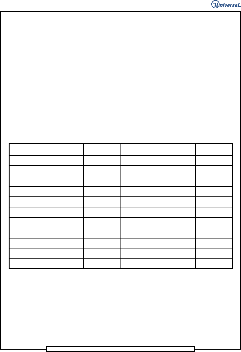
The following table defines the recommended Maintenance Concept for this
assembly. For a more detailed explanation of the Maintenance Concept and
its structure, refer to the Prerequisite Information/Introduction module and
the periodic preventive maintenance described later in this document.
Maintenance Procedures
Recommended
Frequency
Minimum Skill
Required
Spares Kit
Required
Tool Kit
Required
Lubricate tooling driver bodies
500,000
Maintenance
Technicia
n
No No
Remove, disassemble, clean and
lubricate the insertion tooling
3,000,000
Maintenance
Technician
No Yes
Check, clean and lubricate drive pinion
and driver body racks
3,000,000
Maintenance
Technician
No No
Check, clean and lubricate centering
cam surfaces
3,000,000
Maintenance
Technician
No No
Lubricate insertion head lead screw
12,000,000
Maintenance
Technician
No No
Clean the insertion head tooling
housings
12,000,000
Maintenance
Technician
No Yes
Inspect all belts for wear and correct
tension
36,000,000
Maintenance
Technician
Yes No
Remove, disassemble, clean and
lubricate the insertion head
36,000,000
Maintenance
Technician
No Yes
Clean and lubricate the centering
assembly pivot points
36,000,000
Maintenance
Technician
No Yes
Lubricate grease fittings
144,000,000
Maintenance
Technicia
n
No No
Clean and lubricate the lower sprockets
144,000,000
Maintenance
Technician
No No
Page 23
V/S Standard Insertion Head Assembly T50090901 Rev. F
This Document Supports Assembly 50090901 Rev. D
Procedures and Adjustments
Insertion Head Span Axis Adjustment
Purpose:
This procedure ensures that the insertion head span axis is correctly set.
Special Tools:
Set up Tool (43806307 - Large Lead Tooling)
(43806311 - Standard, 5mm and 5.5mm Tooling)
Adjustment Procedure:
1. Push the STOP push button.
2. Palm the machine down as detailed in the Operation Manual.
3. Check that there are no leads or other debris between the flanges and
the stop collar, clean if necessary.
4. Activate the IM Diagnostics as follows. Refer to the IM-UPS and IM
Diagnostics documentation for specific details relating to the operation
of the machine terminal.
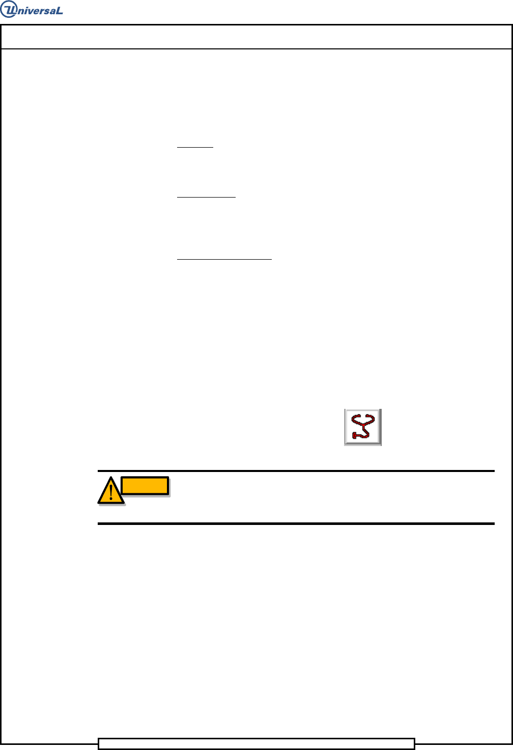
Select the IM Diagnostics icon.
WARNING
When the machine is in the IM Diagnostics function power is provided to
the machine. Exercise caution when performing the following
procedures to avoid Injury to personnel and equipment.
5. Palm the machine up and push the INTLK RESET push button.
6. After the IM Diagnostics has completed its initialization, select the fol-
lowing. Machine Set Up>Critical Axis Positions
Page 24
T50090901 Rev. F V/S Standard Insertion Head Assembly
This Document Supports Assembly 50090901 Rev. D
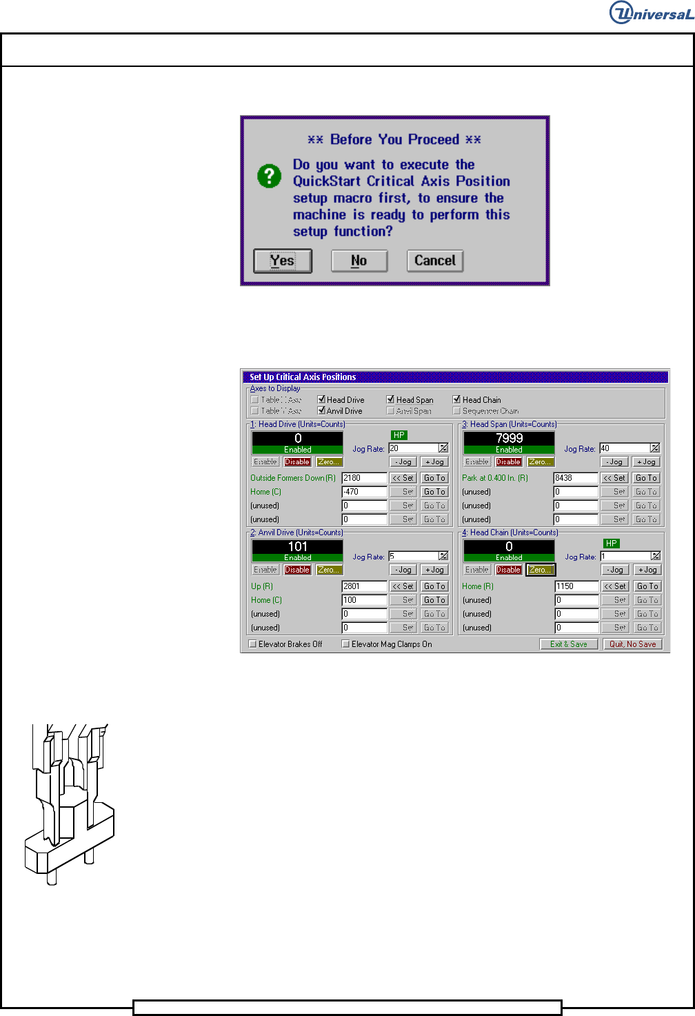
The following message is displayed.
7. Click on Yes. This zeros all axes.
The following screen is displayed
8. In the Set Up Critical Axis Positions screen, select the Head Drive
then click on the Disable button. Manually lower the insertion head
using the 5/16 allen wrench until the outside formers are down.
9. Select the Head Span then click on Enable to enable the span drive.
10. With the set up tool between the outside formers, set the rate to .001
then click on - Jog until the tool is held in position. Click on + Jog un-
til the tool drops from the outside formers. Click on - Jog once.
11. Click on the Set button in the Park at 0.400 In row.
12. Select Exit & Save to save the settings and exit from Set Up Critical
Axis Positions screen.
13. If no additional set ups are to be performed, exit out of the IM Diagnos-
tics function.
End of procedure.