卧式standard头部.pdf - 第68页
Page 66 T50090901 Rev . F V/S Standard Insertion Head Assembly This Document Supports Assembly 50090901 Rev. D Co lla r Clamp Gearb elt Pu lley Thrust Was her Thrust Was her Thrus t Beari ng Cam Drive Key Low e r Sh aft …

Page 65
V/S Standard Insertion Head Assembly T50090901 Rev. F
This Document Supports Assembly 50090901 Rev. D
37. Install the cam shaft assembly through the right side of the housing
then install the centering driven pulley, key and retaining ring to the
left end of the cam shaft.
38. Install the retaining ring on the right end of the cam shaft.
39. Engage the timing belt on the driven pulley, then slide the cam shaft
into the radial bearing in the left side of the housing.
40. Install a radial bearing onto the right end of the cam shaft and into the
right side of the housing.
41. Install the two collar clamps on the ends of the cam shaft. Hand
tighten the collar clamps against the radial bearings then.
42. Adjust the centering driver pulley so it is aligned with the centering
driven pulley and secure the driver pulley in position using the cap
screws.
43. Install the two hex nuts on the two 10-32 x 5/8 socket head cap screws
then install one set in each side of the housing.
44. Spread the centering fingers then install the previously assembled cen-
tering assembly into the housing so the centering fingers engage either
side of the centering cam.
45. Using Loctite 222 on the threads of the two 1/4-20 x 3/4 socket head
cap screws, secure the centering assembly to the housing using the cap
screws and lock washers.
46. Using Loctite 242 on the threads of the 1/4-28 x 1 1/2 button head
screw, install a gear belt pulley into the right idler plate. Secure the
pulley to the plate using the hex jam nut, lock washer and flat washer.
47. Using Loctite 242 on the threads of the 1/4-20 x 1 socket head cap
screw, install the right idler plate assembly to the housing using a split
lock washer and flat washer.
48. Install the 1/4-20 x 2 socket head cap screw, lock washer and flat
washer through the idler plate into the housing. Do not tighten now,
this will be used for later adjustment.
49. Using Loctite 222 on the threads of the two 10-24 x 1 1/2 socket head
cap screws, install the compression spring and spring holder to the
housing using the cap screws.
50. Install the thrust washer, thrust bearing, thrust washer, drive cam key,
and gear belt pulley to the lower shaft. Ensure that there is no axial
play in the shaft assembly before tightening the collar clamp. Secure
the parts on the lower shaft using the screw in the collar clamp.
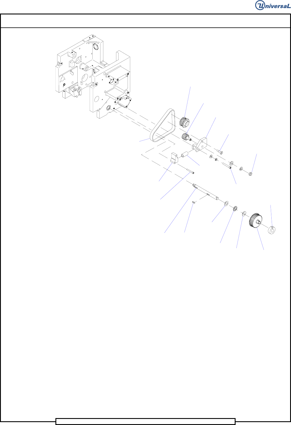
Page 66
T50090901 Rev. F V/S Standard Insertion Head Assembly
This Document Supports Assembly 50090901 Rev. D
Collar
Clamp
Gearbelt
Pulley
Thrust
Washer
Thrust
Washer
Thrust
Bearing
Cam Drive
Key
Lower
Shaft (Ref.)
Socket Head
Cap Screw
Spring
Holder R
Timing Belt
Gearbelt
Pulley (Ref.)
Gearbelt
Pulley
Idler
Plate R
Socket Head
Shoulder Screw
Hex Jam Nut
Socket Head
Cap Screw
Compression
Spring
51. Using Loctite 242 on the threads of the 1/4-28 x 1 1/2 button head
screw, install a gear belt pulley into the left idler plate. Secure the pul-
ley to the plate using the hex jam nut, lock washer and flat washer.
52. Using Loctite 242 on the threads of the 1/4-20 x 1 socket head cap
screw, install the left idler plate assembly to the housing using a split
lock washer and flat washer.
53. Install the 1/4-20 x 2 socket head cap screw, lock washer and flat
washer through the idler plate into the housing. Do not tighten now,
this will be used for later adjustment.
54. Using Loctite 222 on the threads of the two 10-24 x 1 1/2 socket head
cap screws, install the compression spring and spring holder to the
housing using the cap screws.
55. Install the thrust washer, thrust bearing, thrust washer, drive cam key,
and gear belt pulley to the lower shaft. Ensure that there is no axial
play in the shaft assembly before tightening the collar clamp. Secure
the parts on the lower shaft using the screw in the collar clamp.
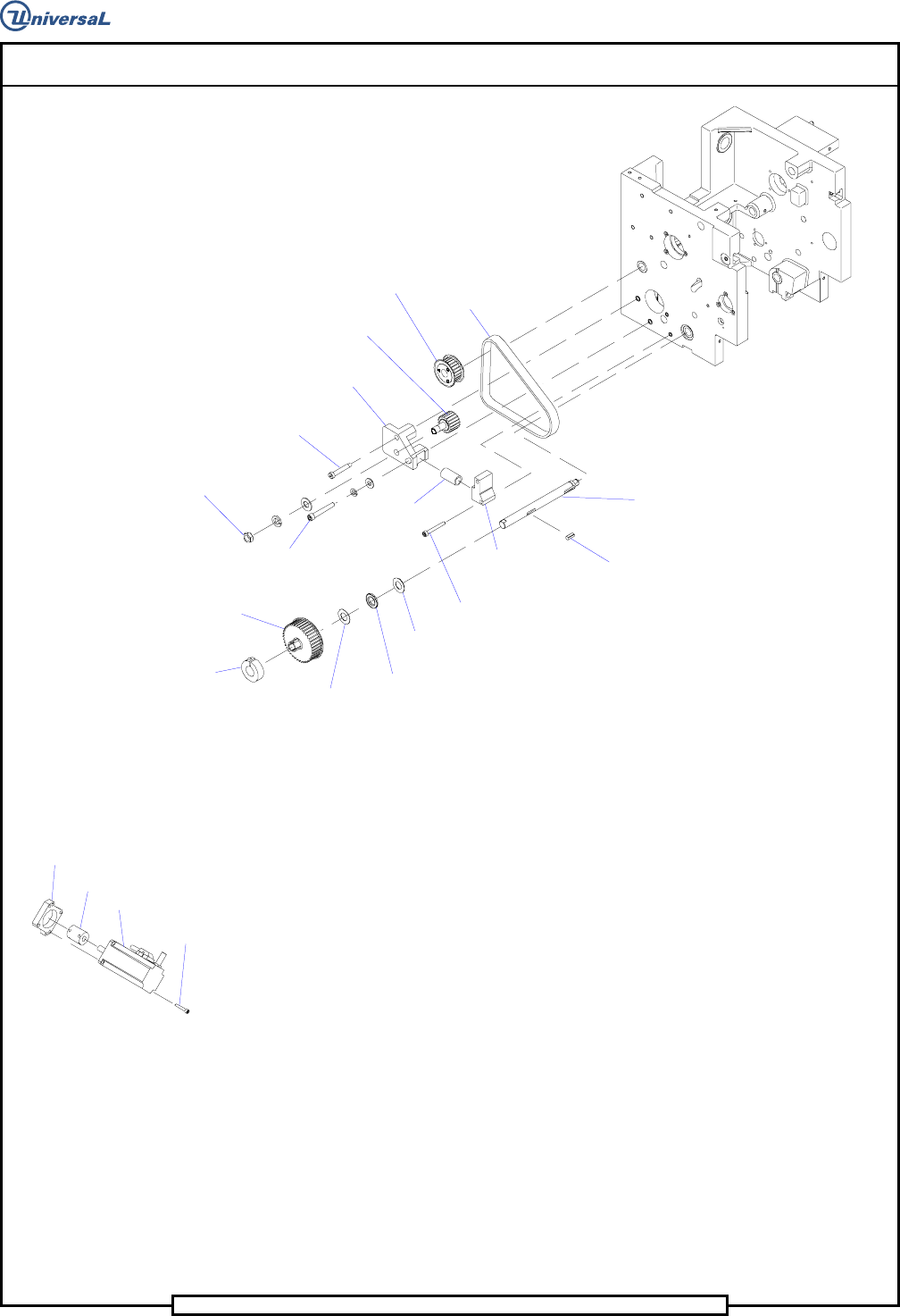
Page 67
V/S Standard Insertion Head Assembly T50090901 Rev. F
This Document Supports Assembly 50090901 Rev. D
Timing
Belt
Gearbelt
Pulley (Ref.)
Gearbelt
Pulley
Idler Plate L
Socket Head
Shoulder Screw
Hex Jam Nut
Socket Head
Cap Screw
Gearbelt
Pulley
Collar
Clamp
Thrust
Washer
Thrust
Washer
Thrust
Bearing
Compression
Spring
Socket Head
Cap Screw
Spring
Holder L
Drive
Cam Key
Lower
Shaft (Ref.)
56. Install a timing belt, on each side of the housing, over the gear belt
drive pulleys, gear belt idler pulleys and onto the lower sprocket gear
belt pulleys.
57. Install the motor bracket and motor for the span axis on the end of the
lead screw, ensuring that the motor shaft engages the coupling on the
lead screw.
Motor
Bracket
Coupling (Ref.)
Span Motor
Socket Head
Cap Screws
58. Using Loctite 222 on the threads of the three 6-32 x 7/8 socket head
cap screws, install the motor and motor bracket to the housing using
the cap screws.
59. Secure the coupling to the motor shaft using the screw in the coupling.
60. Install the motor plate to the housing using 4 1/4-20 x 1 socket head
cap screws and split lock washers.
61. Using Loctite 222 on the threads of the four 10-32 x 3/4 socket head
cap screws, install the motor on the head drive shaft ensuring that the
motor shaft engages the coupling. Secure the motor to the motor plate
using the cap screws.
62. Using Loctite 222 on the threads of the set screw in the coupling, se-
cure the coupling to the motor shaft using the set screw in the coupling.