卧式standard头部.pdf - 第30页
Page 28 T50090901 Rev . F V/S Standard Insertion Head Assembly This Document Supports Assembly 50090901 Rev. D The Set Up Critical Axis Positions screen is displayed. 8. In the Set Up Critical Axis positions screen, sele…
Page 27
V/S Standard Insertion Head Assembly T50090901 Rev. F
This Document Supports Assembly 50090901 Rev. D
Head Height Adjustment
Purpose:
This procedure sets the tooling clearance to the board being processed.
Prerequisites
Head Drive Position Set Up
Anvil Height Adjustment
Adjustment Procedure:
1. Push the STOP button.
2. Palm the machine down as detailed in the Operation Manual.
3. Remove the workboard holders, if mounted, from the X-Y tables.
4. Activate the IM Diagnostics as follows. Refer to the IM-UPS and IM
Diagnostics documentation for specific details relating to the operation
of the machine terminal.
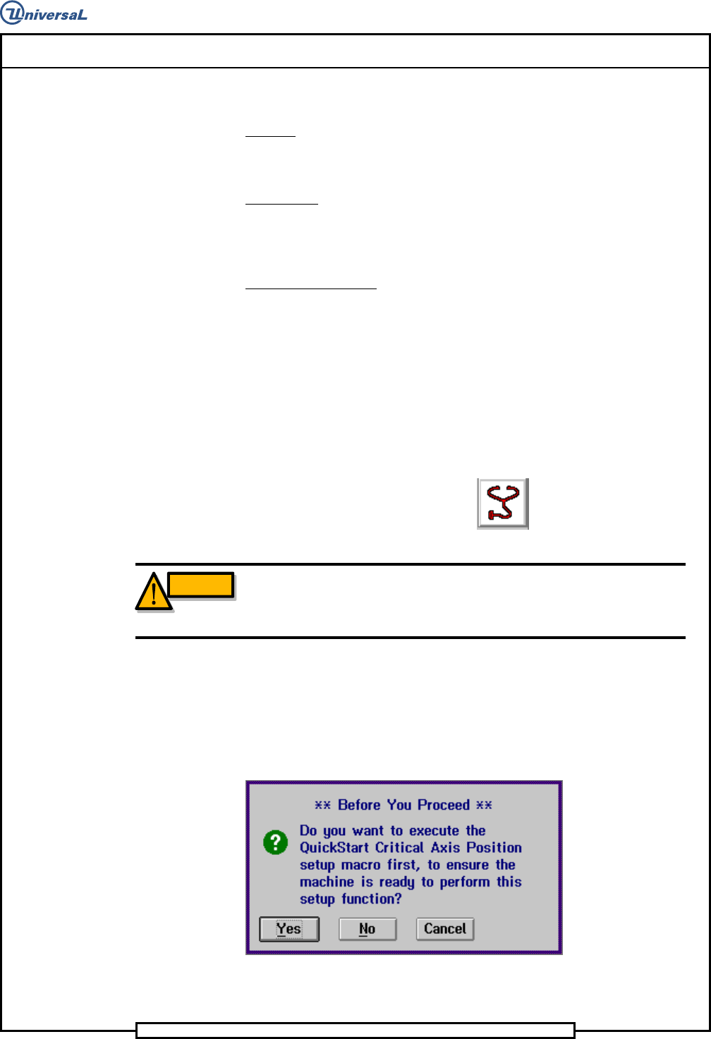
Select the IM Diagnostics icon.
WARNING
When the machine is in the IM Diagnostics function power is provided to
the machine. Exercise caution when performing the following
procedures to avoid Injury to personnel and equipment.
5. Palm the machine up and push the INTLK RESET push button.
6. After the IM Diagnostics has completed its initialization, select the fol-
lowing. Machine Setup>Critical Axis Positions
The following message is displayed.
7. Click on Yes. This zeros all axes.
Page 28
T50090901 Rev. F V/S Standard Insertion Head Assembly
This Document Supports Assembly 50090901 Rev. D
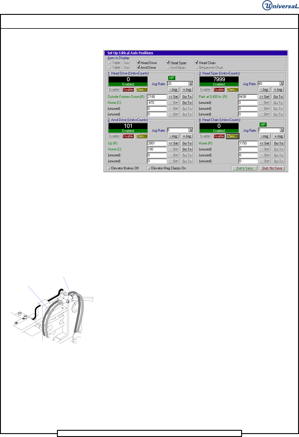
The Set Up Critical Axis Positions screen is displayed.
8. In the Set Up Critical Axis positions screen, select Head
Drive>Enable then Go To in the Outside Formers Down row to
drive the head tooling down.
9. In the Set Up Critical Axis positions screen, select Anvil
Drive>Enable then Go To in the Up row to drive the anvils up.
10. Check the clearance between the bottom of the outside formers and the
top of the anvils. If the dimension equals the nominal board thickness
plus .009 +/- .001 inches (0,23mm +/- 0,025mm), no adjustment is re-
quired. If the dimension is not correct, proceed as follows.
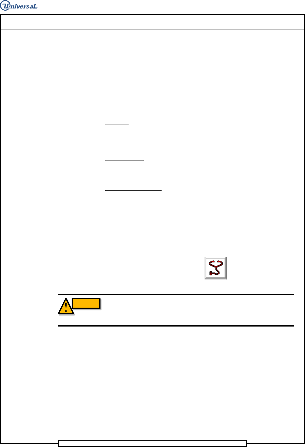
11. Loosen the four screws retaining the head to the mounting plate
enough to allow vertical movement of the head on the plate when turn-
ing the height adjusting jack screw.
Four head
mounting screws
Jacking Screw
12. Lower the insertion head below the desired setting by turning the
height adjusting jack screw clockwise.
13. Raise the head by turning the height adjustment jack screw counter-
clockwise until a dimension of .002 inch (0,05mm) less than the calcu-
lated dimension in step 10 is attained. When the upper screws are
tightened, this will provide the calculated dimension in step 10.
14. Torque the four screws retaining the head to the mounting plate to 40
ft/lbs, then check that the clearance dimension is correct.
15. In the Set Up Critical Axis screen click on the Zero buttons for the
Head Drive and Anvil Drive several times to cycle the head and clinch
then verify the head height adjustment. If incorrect, repeat the proce-
dure and recheck.
Page 29
V/S Standard Insertion Head Assembly T50090901 Rev. F
This Document Supports Assembly 50090901 Rev. D
16. Click on the Quit, No Save button to exit out of the Set Up Critical
Axis Position screen.
17. With the tooling raised and if no additional set ups are to be performed,
exit out of the IM Diagnostics function.
End of procedure.
Head Chain to Tooling Alignment
Purpose:
To position the chain so the V slot in the carrier clips aligns exactly with the
V slot in the head tooling and the chain clips are aligned horizontally.
Special Tools:
Gauge Pin (.039 inch diameter - 40968505)
Adjustment Procedure:
1. Push the STOP push button.
2. Palm the machine down as detailed in the Operation Manual.
3. Activate the IM Diagnostics as follows. Refer to the IM-UPS and IM
Diagnostics documentation for specific details relating to the operation
of the machine terminal.
Select the IM Diagnostics icon.
WARNING
When the machine is in the IM Diagnostics function power is provided to
the machine. Exercise caution when performing the following
procedures to avoid Injury to personnel and equipment.
4. Palm the machine up and push the INTLK RESET push button.
5. After the IM Diagnostics has completed its initialization, select the fol-
lowing. Machine Set Up>Critical Axis Positions