卧式standard头部.pdf - 第57页
Page 55 V/S Standard Insertion Head Assembly T50090901 Rev . F This Document Supports Assembly 50090901 Rev. D Shear Bl ade Outsid e Form er Driver Tip Detents Driver Body Com pre ssi on Spring S pr ing H o lder Fl at Wa…
Page 54
T50090901 Rev. F V/S Standard Insertion Head Assembly
This Document Supports Assembly 50090901 Rev. D
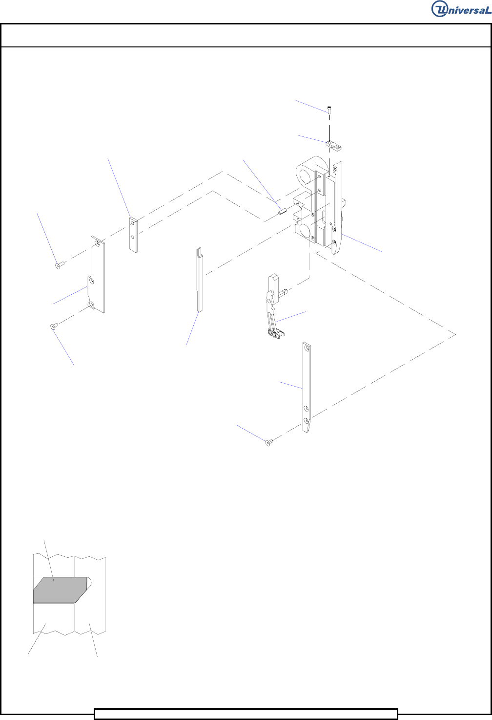
12. Using Loctite 222 on the threads of the two 4-40 x 3/8 socket head cap
screws, install the plate to the tooling housing using the cap screws.
Spring Pin
Spacer Plate
Flat Head Screw
Flat Head Screw
Rear Rail
Cam Rail
Kick Out Arm
Assembly
Front Rail
Flat Head Screw
Socket Head
Cap Screw
Plate
Tooling
Housing
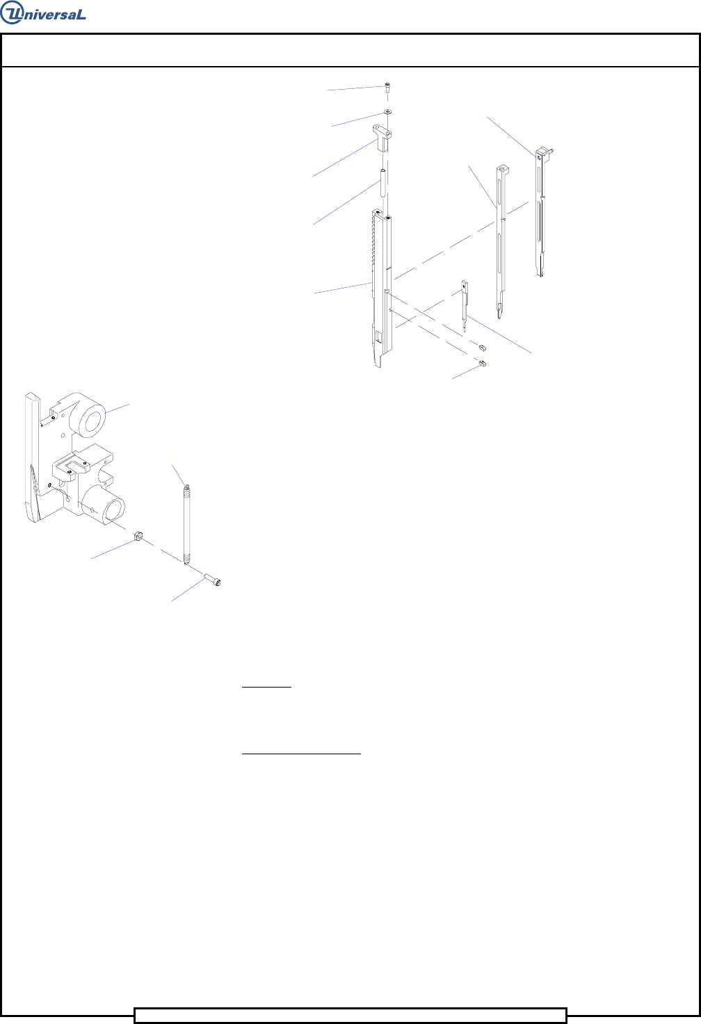
13. Lightly lubricate the compression spring with Kluber Syntheso D32
then install the compression spring and spring holder in the driver
body. Using Loctite 222 on the threads of the two 4-40 x 3/8 socket
head cap screws, secure the spring holder to the driver body using the
cap screws and flat washers.
14. Lightly lubricate the driver body with Kluber Syntheso D32. Leave the
gear racks dry at this time, these will be lubed by the pinion contact
surface later in the head assembly.
15. Lightly lubricate the driver tip, outside former and shear blade with
Kluber Syntheso D32 then install the driver tip, outside former and
shear blade into the driver body.
Detent
Driver Body
Former
16. Lubricate the detents with Kluber Syntheso D32 then install the detents
into the driver body with the chamfers on the detents oriented as
shown.
Page 55
V/S Standard Insertion Head Assembly T50090901 Rev. F
This Document Supports Assembly 50090901 Rev. D
Shear Blade
Outside
Former
Driver Tip
Detents
Driver Body
Compression
Spring
S
pring Holder
Flat Washer
Socket Head
Cap Screw
17. Using Loctite 222 on the threads of the 8-32 x 5/8 socket head cap
screw, install the cap screw, one end of the extension spring and hex
nut into the housing. Do not attach the other end of the spring at this
time.
Hex Nut
Socket Head
Cap Screw
Tooling
Housing
Extension
Spring
18. Place the assembled tooling aside, it will be installed into the tooling
housing during the insertion head assembly procedure.
19. Assemble the opposite side tooling housing assembly as detailed
above then set both assemblies aside.
End of procedure.
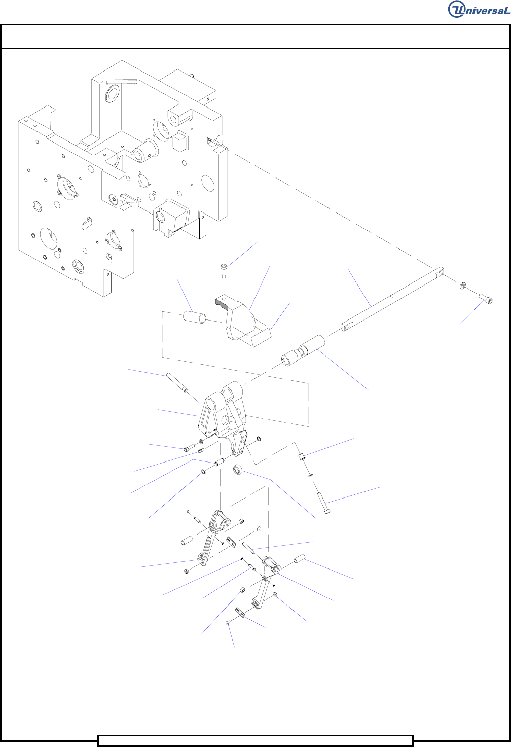
Centering Assembly
Purpose:
The following procedure presents the steps required for centering assembly.
Assembly Procedure:
1. Using Loctite 222 on the threads of the two 4-40 x 5/16 socket flat
head screws, install the centering inserts to the centering fingers using
the flat head screws and hex nuts. Clean screws with primer N, before
applying loctite.
2. Install a radial bearing in each centering finger. Slide the finger pivot
pin through the centering finger and radial bearing, then secure them
in position using the retaining rings.
3. Position the centering fingers, pinion pin, and compression springs in
the centering housing so the compression springs engage the indents
in the fingers and the housing. Apply Magnalube to the finger shafts
and pivot areas of both centering fingers, then insert the shafts into the
housing so they engage the centering fingers.
Page 56
T50090901 Rev. F V/S Standard Insertion Head Assembly
This Document Supports Assembly 50090901 Rev. D
Compression
Spring
Shoulder Screw
Spring Support
Key
Pivot Shaft
Eccentric
Bushing
Socket Head
Cap Screw
Bushing
Socket Head
Cap Screw
Radial Bearing
Radial Bearing
Compression
Spring
Centering
Finger RH
Centering
Finger LH
Hex Nut
Centering
Insert
Socket Flat
Head Screw
Finger
Pivot Pin
Retaining
Ring
Retaining
Ring
Follower
Pin
Hex Nut
Socket Head
Cap Screw and
Lock Washer
Centering
Housing
Finger
Shaft
Pinion Pin
Do Not Grease
Leadscrew
Label