卧式standard头部.pdf - 第3页
Page 1 V/S Standard Insertion Head Assembly T50090901 Rev . F This Document Supports Assembly 50090901 Rev. D

i
V/S Standard Insertion Head Assembly T50090901 Rev. F
This Document Supports Assembly 50090901 Rev. D
Table of Contents
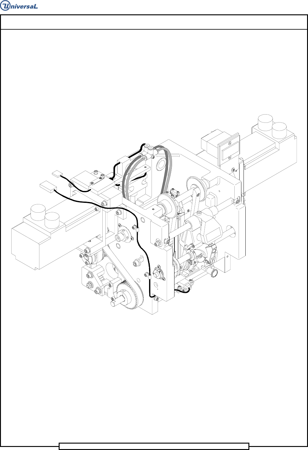
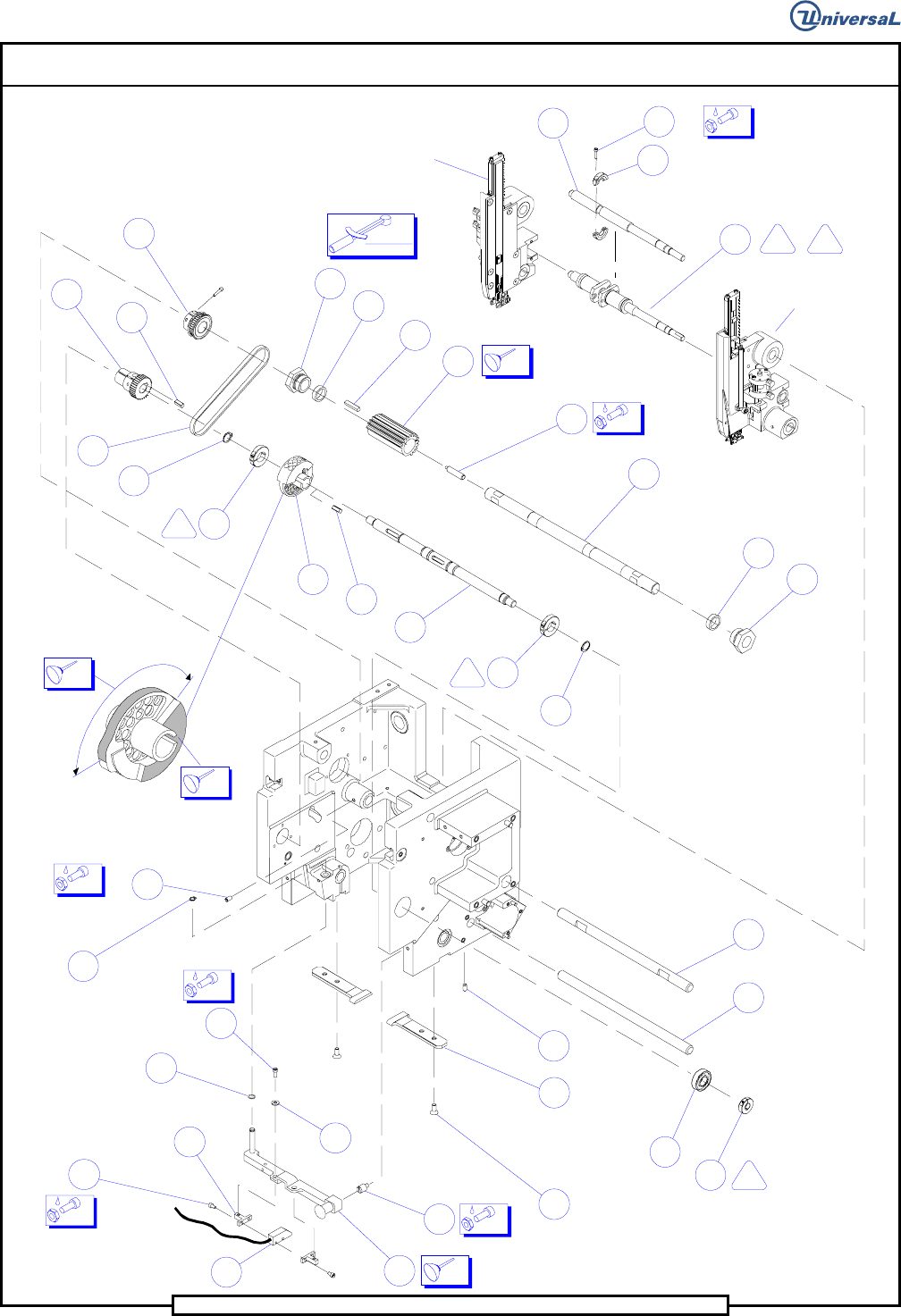
Assembly Drawings....................................................................................................................................................... 1
Notes .................................................................................................................................................................. 13
Adhesives and Lubricants .................................................................................................................................. 14
Bill Of Materials ................................................................................................................................................ 15
Functional Description ................................................................................................................................................ 22
Maintenance Concept .................................................................................................................................................. 22
Procedures and Adjustments ....................................................................................................................................... 23
Insertion Head Span Axis Adjustment............................................................................................................... 23
Head Drive Position Set up................................................................................................................................ 25
Head Height Adjustment ................................................................................................................................... 27
Head Chain to Tooling Alignment .................................................................................................................... 29
Part Missing Detector Adjustment..................................................................................................................... 31
Tensioning Head Chain Belts ............................................................................................................................ 34
Drive Belt ................................................................................................................................................. 34
Idler Belts ................................................................................................................................................. 34
Centering Adjustments ...................................................................................................................................... 35
Cam Orientation ....................................................................................................................................... 35
Cam Alignment ........................................................................................................................................ 37
Centering Finger Alignment .................................................................................................................... 38
Centering Finger Height Adjustment ....................................................................................................... 40
Centering Fingers Inward Adjustment ..................................................................................................... 42
Cam Timing.............................................................................................................................................. 45
Head Disassembly.............................................................................................................................................. 47
Ball Bushing Shaft Checks....................................................................................................................... 49
Ball Bushing Preload Adjustment ............................................................................................................ 50
Lead Screw Flanged Bushing Checks ...................................................................................................... 50
Inside Former Check ................................................................................................................................ 50
Shear Block Check ................................................................................................................................... 51
Insertion Head Assembly................................................................................................................................... 52
Tooling Housing Assembly...................................................................................................................... 52
Centering Assembly ................................................................................................................................. 55
Head Assembly ........................................................................................................................................ 57
Preventive Maintenance Schedule............................................................................................................................... 72
Changes To This Revision........................................................................................................................................... 76
Page 2
T50090901 Rev. F V/S Standard Insertion Head Assembly
This Document Supports Assembly 50090901 Rev. D
96
50
43
197
111
92
102
97
102
90
111
197
51
40
71
46
47
40
51
38
11
(2)
172
(2)
127
195
134
(2)
172
98
99
(4)
142
(2)
124
33
(4)
185
(2) 143
(L.H. Tooling Housing)
(R.H. Tooling
Housing)
14
14
04
04
04
04
04
41
110
2
2
126
2
1
(2)
182
14
(outside circumference
between arrows)
(high lobe on cam - both sides)
14
15
100 IN-LB
11,3 NM
(Shown without
flanged bushings)
(2)140
115
04
50 (Ref)