卧式standard头部.pdf - 第27页
Page 25 V/S Standard Insertion Head Assembly T50090901 Rev . F This Document Supports Assembly 50090901 Rev. D Head Drive P osition Set up Purpose: Head drive critical axis position set up is required after drive pinion …
Page 24
T50090901 Rev. F V/S Standard Insertion Head Assembly
This Document Supports Assembly 50090901 Rev. D
The following message is displayed.
7. Click on Yes. This zeros all axes.
The following screen is displayed
8. In the Set Up Critical Axis Positions screen, select the Head Drive
then click on the Disable button. Manually lower the insertion head
using the 5/16 allen wrench until the outside formers are down.
9. Select the Head Span then click on Enable to enable the span drive.
10. With the set up tool between the outside formers, set the rate to .001
then click on - Jog until the tool is held in position. Click on + Jog un-
til the tool drops from the outside formers. Click on - Jog once.
11. Click on the Set button in the Park at 0.400 In row.
12. Select Exit & Save to save the settings and exit from Set Up Critical
Axis Positions screen.
13. If no additional set ups are to be performed, exit out of the IM Diagnos-
tics function.
End of procedure.
Page 25
V/S Standard Insertion Head Assembly T50090901 Rev. F
This Document Supports Assembly 50090901 Rev. D
Head Drive Position Set up
Purpose:
Head drive critical axis position set up is required after drive pinion reassem-
bly and insert drive servo motor reassembly.
Special Tools:
None
Adjustment Procedure:
1. Push the STOP button.
2. Palm the machine down as detailed in the Operation Manual.
3. Remove the workboard holders, if mounted, from the X-Y tables.
4. Activate the IM Diagnostics as follows. Refer to the IM-UPS and IM
Diagnostics documentation for specific details relating to the operation
of the machine terminal.
Select the IM Diagnostics icon.
WARNING
When the machine is in the IM Diagnostics function power is provided to
the machine. Exercise caution when performing the following
procedures to avoid Injury to personnel and equipment.
5. Palm the machine up and push the INTLK RESET push button.
6. After the IM Diagnostics has completed its initialization, select the fol-
lowing. Machine Setup>Critical Axis Positions
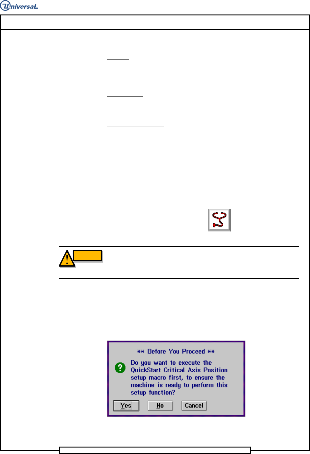
The following message is displayed.
7. Click on Yes. This zeros all axes.
Page 26
T50090901 Rev. F V/S Standard Insertion Head Assembly
This Document Supports Assembly 50090901 Rev. D
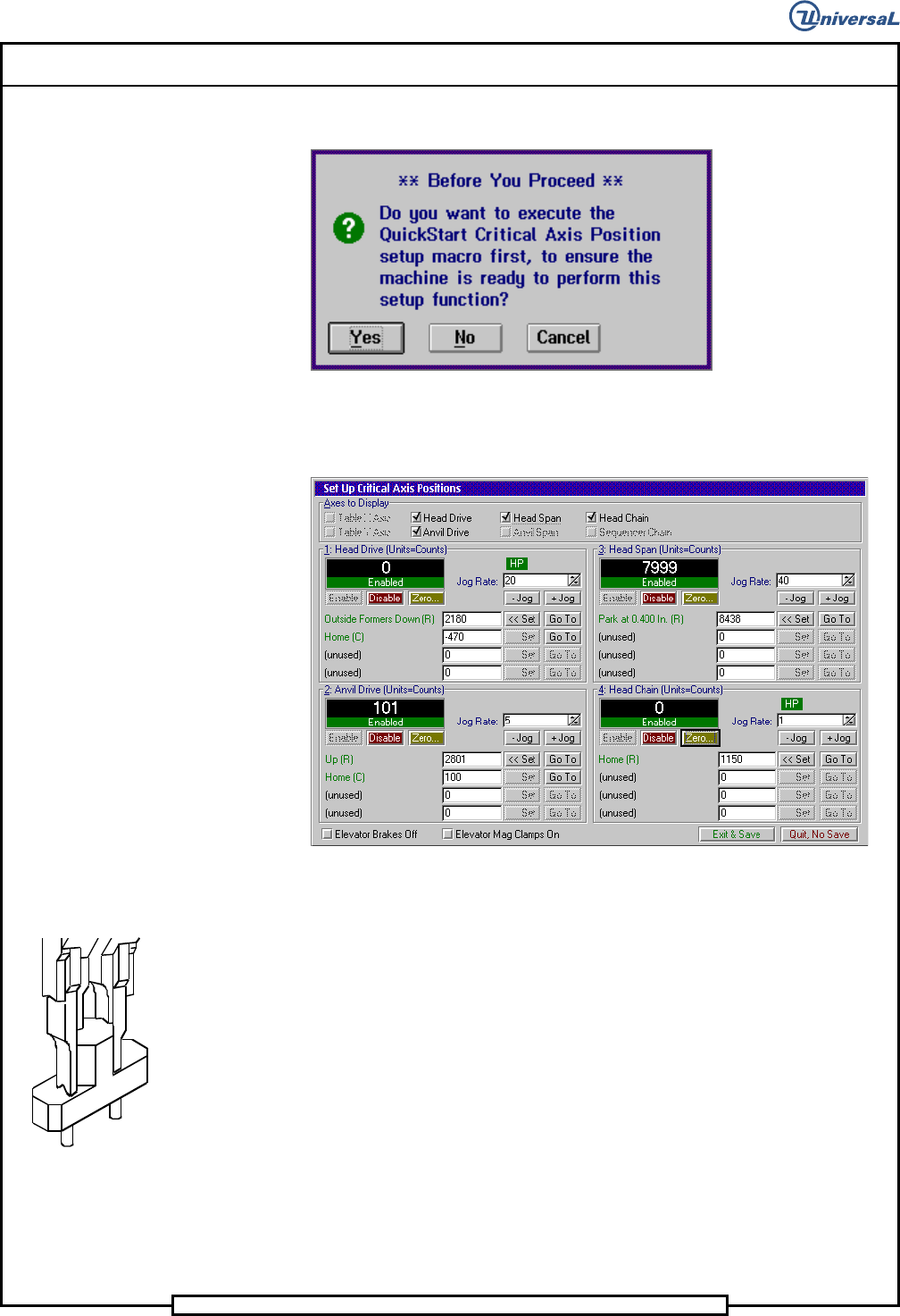
The Set Up Critical Axis Positions screen is displayed.
8. In the Set Up Critical Axis positions screen, select Head
Drive>Disable to disable the head.
NOTE
If the unit of measurement is not in counts, right click on the rate field
and select Axis Position in Counts.
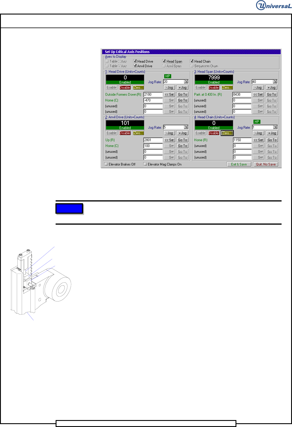
9. Using the 5/16 allen wrench, manually rotate the drive shaft so the out-
side formers just contact the shear blade and are fully lowered. Fully
lowered occurs just before the compression spring starts to compress.
10. Raise and lower the tooling while observing the Position Display.
Verify that the counts in the field do not vary more than three counts
each time the outside formers are lowered.
Compression
Spring
Outside Former
Tooling Housing
Shear Blade
11. When the outside formers down position is verified, click on the Set
button in the Outside Formers Down row.
12. Select Exit & Save to save the settings and exit from Set Up Critical
Axis Positions screen.
13. If no additional set ups are to be performed, exit out of the IM Diag-
nostics function.
End of procedure.