卧式standard头部.pdf - 第73页
Page 71 V/S Standard Insertion Head Assembly T50090901 Rev . F This Document Supports Assembly 50090901 Rev. D 78. Using Loctite 222 on the threads of the 6-32 x 1-1/2 socket head cap screw, install the 2 tee fittings to…
Page 70
T50090901 Rev. F V/S Standard Insertion Head Assembly
This Document Supports Assembly 50090901 Rev. D
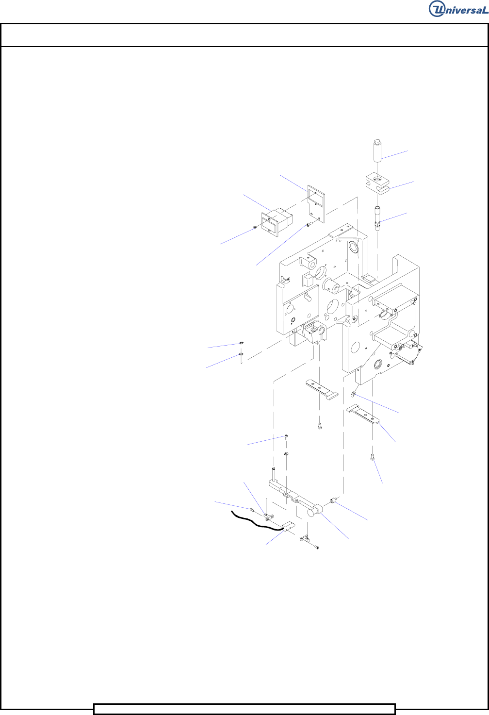
74. Apply Magnalube to the pin of the BEC bracket assembly then install
the BEC bracket assembly into the housing and secure it in position us-
ing the spring washer and the retaining ring.
75. Using Loctite 222 on the threads of the locator pin, install the locator
pin in the housing.
Retaining
Ring
Spring
Washer
Socket Head
Cap Screw
Socket Button
Head Screw
Socket Head
Cap Screw
Socket Flat
Head Screw
Socket Head
Cap Screw
Light Source
Block
BEC Bracket
Luminator
Assembly
Locator Pin
Chain Clip
Guide
Grease Fitting
Jack Screw
Adjusting
Block
Jack
Impulse
Counter
Head Counter
Bracket
76. Install the grease fittings into the housing. Using the grease gun with
Ultra blue grease, apply the grease to the grease fittings until a slight
amount of grease is seen at the spacers.
77. Install the required icor clamps to the housing using 8-32 x 3/8 socket
head cap screws with loctite 222. All systems require 3 3/16 inch
clamps on the left side of the housing, and systems equipped with an
expanded range verifier require 3 additional clamps on the right side of
the housing. Refer to the assembly drawings section in the front of this
document for locations.
Page 71
V/S Standard Insertion Head Assembly T50090901 Rev. F
This Document Supports Assembly 50090901 Rev. D
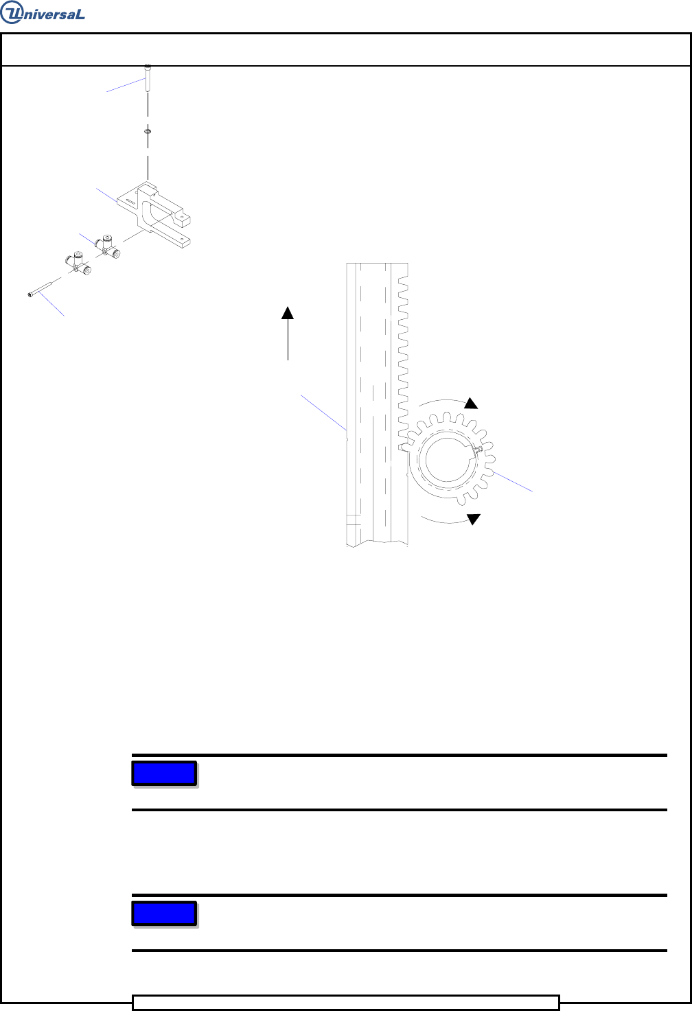
78. Using Loctite 222 on the threads of the 6-32 x 1-1/2 socket head cap
screw, install the 2 tee fittings to the missing part detector assembly.
Install the missing part detector assembly to the housing using the 2
10-24 x 1-1/2 socket head cap screws and lock washers.
Socket Head
Cap Screw
Socket Head
Cap Screw
T
ee Fitting
Missing Part
Detector Assembly
79. Install the ends of the fiber optic cables flush with the surface of the
missing part detector. Install the fiber optic cables so there is a dimen-
sion of 7.00 +/- .06 inch from the edge of the sensor assembly to the
end of the cable. Refer to the assembly at the front of this document
for details on the sensor cable assembly.
Drive Pinion
Driver Body
Tooling Timing
Alignment
Rotate Pinion in this direction
to allow driver body insertion
Driver Body
Extended Up
Rotate Pinion in this direction
to engage with driver body
80. Rotate the pinion shaft, as shown above, so the smooth side of the pin-
ion is visible. Insert the assembled tooling into the tooling housings.
81. While holding the two driver bodies extended in the up position, ro-
tate the pinion, as shown above, and engage the first tooth on the
driver bodies with the first tooth on the pinion.
82. Manually rotate the pinion shaft until the tooling is in the full down
position (the 5/16 allen wrench may be needed).
NOTE
This step ensures that the cam follower is on the proper side of the cam
lobe when the head drive axis is zeroed.
83. Attach the loose end of the extension springs to the pins on the shear
blades.
NOTE
Refer to the assembly at the beginning of this document for details
pertaining to the routing of the electrical and pneumatic lines.
End of procedure.

Page 72
T50090901 Rev. F V/S Standard Insertion Head Assembly
This Document Supports Assembly 50090901 Rev. D
Preventive Maintenance Schedule
WARNING
Do not perform any preventive maintenance with power on unless
specifically instructed otherwise. Failure to observe this warning may
result in personal injury.
CAUTION
When performing machine maintenance, wear a wrist strap connected to
ground to prevent electrostatic discharge damage to printed circuit
boards.
CAUTION
Failure to use Kluber Syntheso D32 oil as stated in our machine
maintenance schedules leads to reduced tooling life and/or failure.
Syntheso D32 is a special blend specifically designed for high speed
moving and mating metal parts. No other oil is recommended.
500,000 Cycles (Maintenance Interval 1)
Check: Perform Maintenance:
1. Apply 2 drops of Kluber Syntheso D32 to the
exposed side of the driver bodies. Removal is
not required.
3,000,000 Cycles (Maintenence Interval 2)
Check: Perform Maintenance:
1. Remove, disassemble, clean and lubricate with
Kluber Syntheso D32 to the insertion head
tooling; including the kick-out arms and
compression springs.
2. Check the pinion and racks on the driver 2. Clean and lubricate the pinion and racks with
bodies for residue. a light coat of Magnalube grease.
3. Check the contact surfaces of the 3. Clean and lubricate the cam surfaces with a light
centering cam. coat of Magnalube grease.