卧式standard头部.pdf - 第61页
Page 59 V/S Standard Insertion Head Assembly T50090901 Rev . F This Document Supports Assembly 50090901 Rev. D 4. Apply a light coating of Magnalube on the teeth of pinion, then place a .190 key into the keyway on the sh…
Page 58
T50090901 Rev. F V/S Standard Insertion Head Assembly
This Document Supports Assembly 50090901 Rev. D
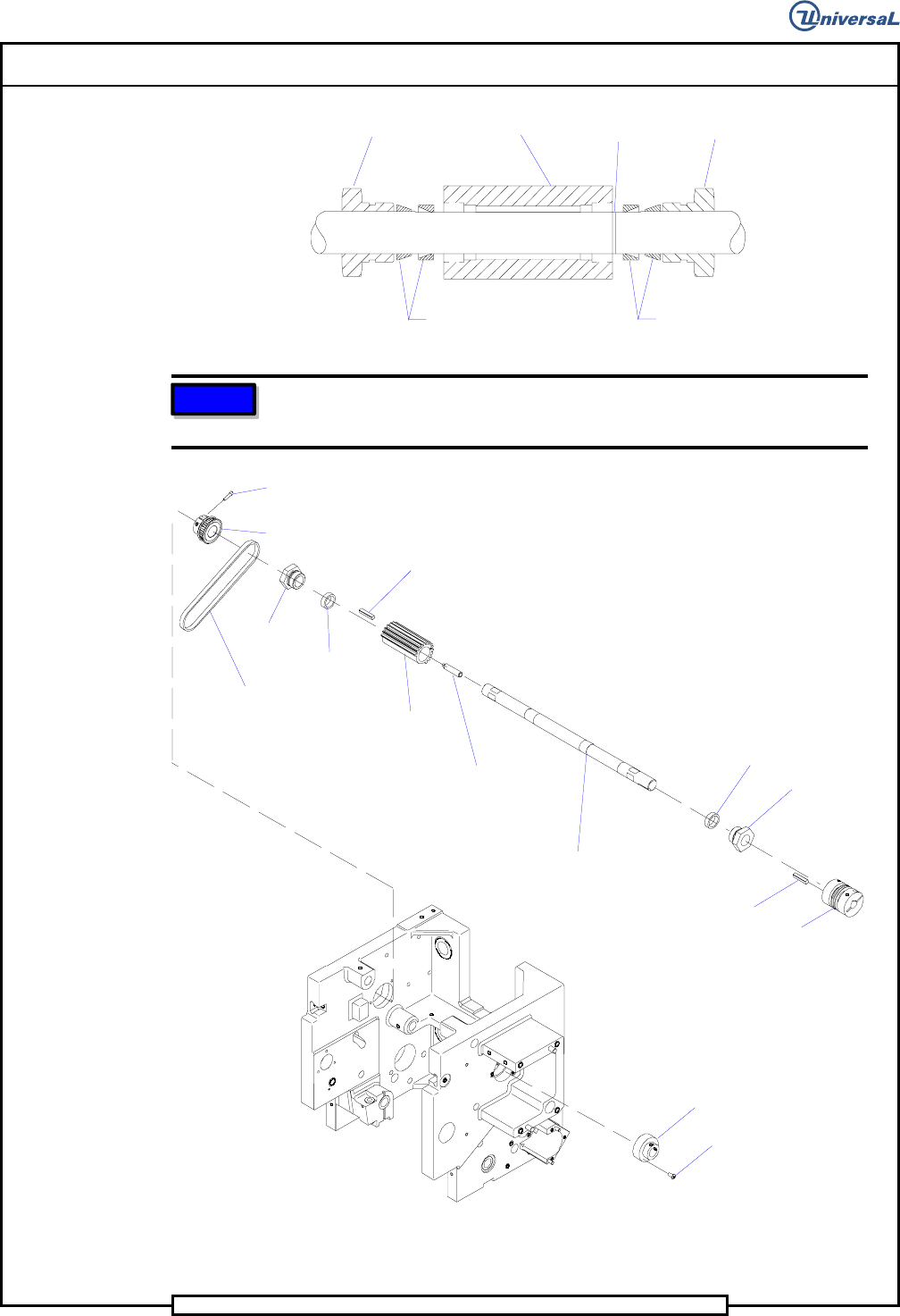
Lock nut
Pinion
Pinion location
groove
Lock nut
Locking
element
Locking
element
NOTE
The pinion has an R on one end. The end marked R must be installed
on the shaft toward the right side of the insertion head assembly.
Locknut
Ball Bearing
Clamp
Socket Button
Head Screw
Spring Plunger
Pinion Shaft
Pinion
.190 Key
Locking
Element
Locking
Element
Locknut
Timing Belt
Socket Head
Cap Screw
Centering Driver
Pulley
Coupling
.190 Key
Page 59
V/S Standard Insertion Head Assembly T50090901 Rev. F
This Document Supports Assembly 50090901 Rev. D
4. Apply a light coating of Magnalube on the teeth of pinion, then place
a .190 key into the keyway on the shaft. Slide the pinion over the key
while ensuring the R stamped on the end of the pinion is on the right
side of the shaft. Slide another locking element and locknut into posi-
tion on the shaft.
5. Continue to slide the assembled shaft into the housing until the ends
extend equally from the outer surfaces of the bearings. Tighten the set
screws of the ball bearing clamp onto the flats of the pinion shaft.
6. Use the 1-1/8 inch wrench (47146101) to hold the left hand nut on the
pinion and apply 100 in-lbs of torque to the hex end of the pinion drive
shaft. Repeat this step for the right hand nut on the pinion.
7. Install the two 6-32 x 1/2 socket head cap screws in the centering
driver pulley but do not tighten at this time. The driver pulley will be
aligned with the driven pulley later.
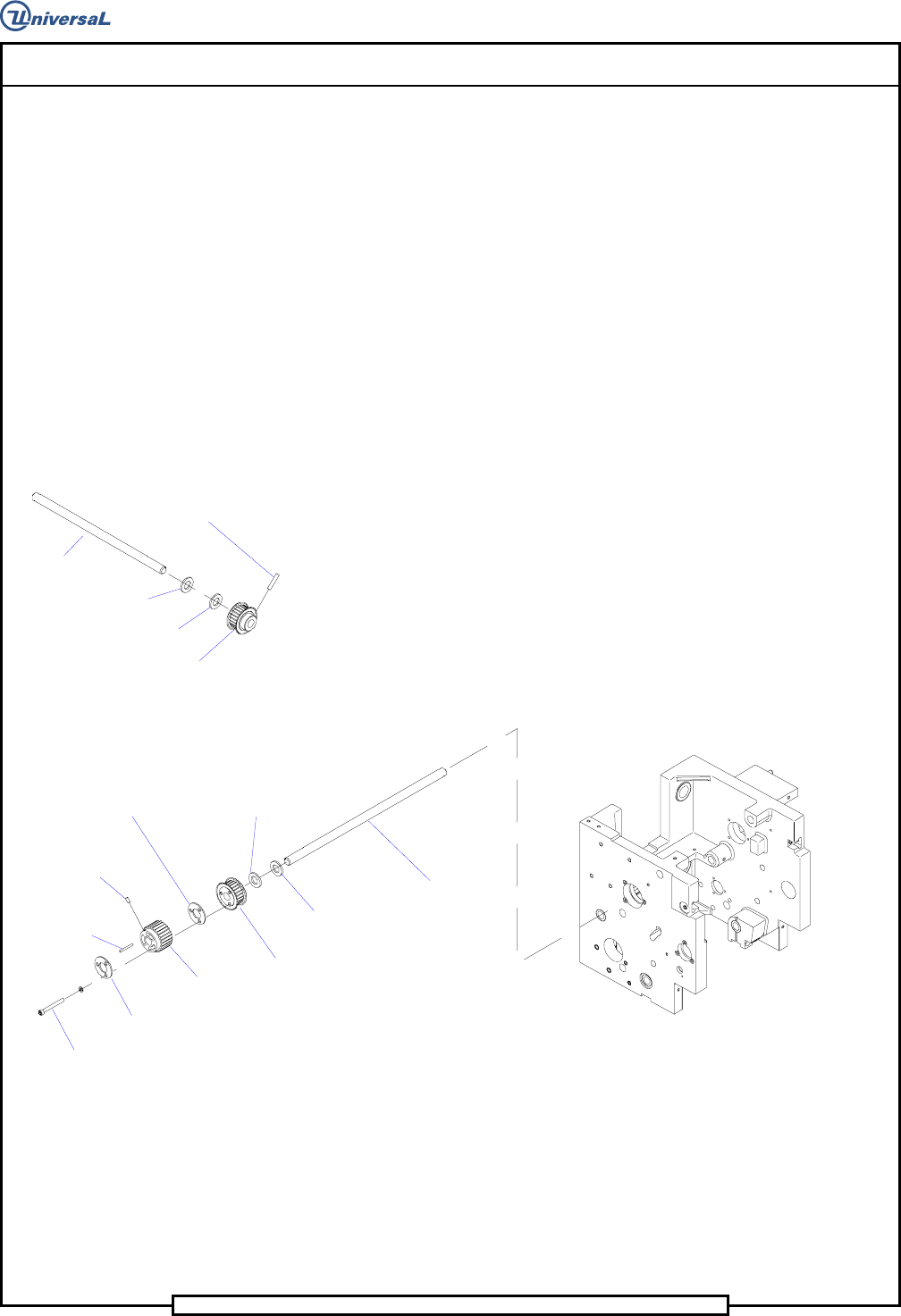
Thrust Washer
Gear Belt Pulley
Spring Pin
Shaft
Thrust Bearing
8. Install the coupling and a .190 key on the right end of the pinion shaft.
Use Loctite 222 on the threads of the screw in the left side of the cou-
pling, and tighten the screw to secure the coupling to the drive shaft.
9. Install the thrust bearing, thrust washer and gear belt pulley on the end
of the shaft. Align the hole in the shaft with the hole in the pulley, then
secure the pulley to the shaft using a .187 x 1.00 spring pin.
10. Slide the shaft assembly into the right side of the housing and fully
through the housing so the thrust bearing contacts the housing.
Set Screw
.125 Key
Socket Head
Cap Screw
Gear Belt
Pulley
Gear Belt
Pulley
Plate Washer
Plate Washer
Thrust
Bearing
Shaft
Thrust
Washer
11. On the other end of the shaft, install a thrust bearing, thrust washer,
gear belt pulley, plate washer, gear belt pulley, .125 key, and plate
washer. Secure the parts on the shaft using 3 10-24 x 1 3/4 socket head
cap screws and split lock washers.
12. Using Loctite 222 on the threads of the 8-32 x 3/8 set screw, secure the
gear belt pulley to the shaft using the set screw. All side play should
be eliminated.
Page 60
T50090901 Rev. F V/S Standard Insertion Head Assembly
This Document Supports Assembly 50090901 Rev. D
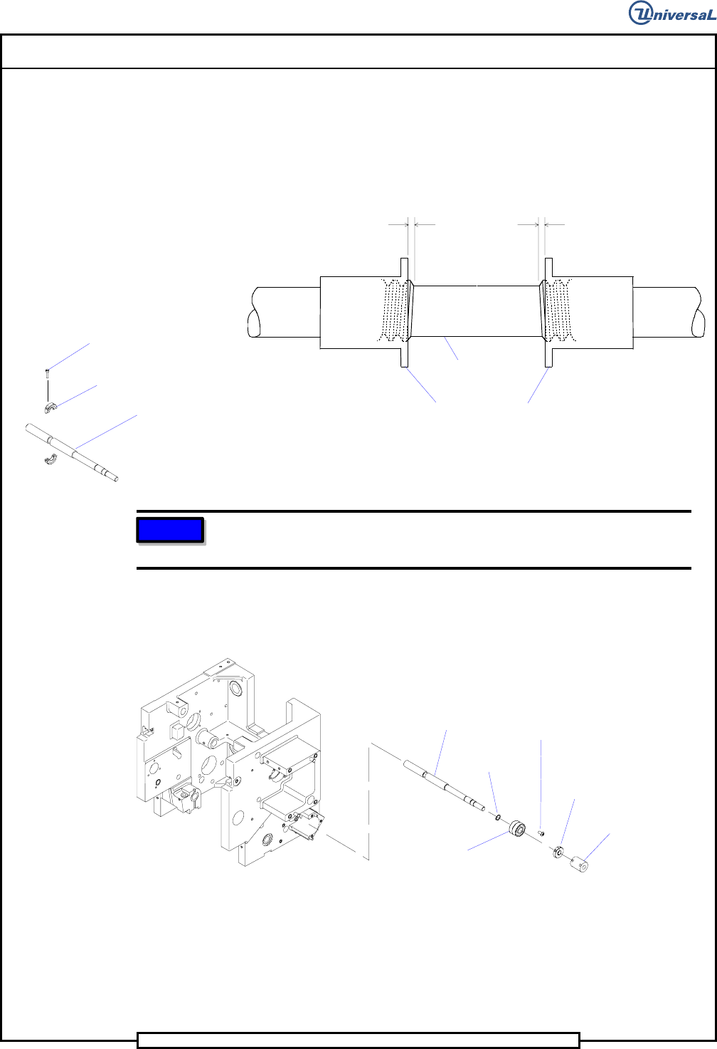
13. Thread the left-hand and right-hand flanged bushings towards each
other until each is an equal distance from the center hole in the lead
screw shaft. Note the orientation of the bushings for proper installation
into the tooling housings. While maintaining the bushing orientation,
thread the bushings apart until the left side bushing end reaches the
end of the lead screw shaft.
Equal threads
visible on each
flanged bushing.
Lead Screw
Flanged Bushings
Socket Head
Cap Screw
Zero Span Stop
Lead Screw
14. Using Loctite 222 on the threads of two 4-40 x 1/2 socket head cap
screws, secure the zero span stop to the lead screw using the cap screws.
Ensure that the zero span stop floats freely on the lead screw.
NOTE
The lead screw and bushings are coated with TFE and do not require
lubrication.
Do not grease the lead screw and bushings.
15. Place the retaining ring on the lead screw.
Ball Bearing
Retaining
Ring
Socket Button
Head Screw
Coupling
Collar
Clamp
Lead Screw
16. Using loctite 222 on the threads of 4 6-32 x 3/8 socket button head
screws, finger tighten the flanged bushings to the tooling housings.
17. Install the lead screw through the casting right side wall.
18. Using Loctite 222 on the threads of the three 8-32 x 3/8 socket button
head screws, install the ball bearing into the housing using the button
head screws.