Hybridklemmung mit Vakuumabfrage (Funktionsbeschreibung).pdf - 第30页
F unctional description - Special design for the hybrid clamping unit with vacuum check 02/2006 Edition 30 2.2 Require ments Hardware: SIPLACE S-25 HM 2 Sof tware: No special requirements 2 2.2.1 Activating the vacuum to…

Functional description - Special design for the hybrid clamping unit with vacuum check
02/2006 Edition
29
2 Special design for hybrid clamping unit with
vacuum check
2.1 Safety instructions
WARNING
The safety instructions from the “Operational safety” chapter of the user manual and servicing in-
structions take precedence over these instructions. 2
The SIPLACE placement machines are supplied with mains voltage.
Consequently parts of these systems carry dangerous voltages! This voltage is present at certain
modules inside the machine base, even when the machine is switched off at the main power
switch.
Incorrect handling of the placement machine or touching live parts of the machine can result in
death or severe injury, and considerable damage to equipment.
BEFORE starting any work, shut down the operating system correctly, then switch the machine
OFF at the main power switch and disconnect from the main power supply. In addition, the com-
pressed air supply must be switched off at the compressed air unit's main valve in the machine
base and vented by actuating the needle valve on the compressed air unit.
There is DANGER for heart pacemaker wearers in the vicinity of the linear motors, as described
in detail in the "Special safety instructions for working in the vicinity of strong magnetic fields"
section of the user manual and service manual.
Always follow the accident prevention regulations, DIN or other standards and special safety
rules applicable in your country.
Pay attention to the information concerning residual voltages in the Operational Safety chapter.
Follow the ESD regulations as described in the operational safety section of the operating
instructions.
During the retrofit, always secure the machine to prevent access by other people and to prevent
it being switched on again. The procedure is described in the “Locking the machine…” section of
the user manual.
Working with the SITEST program further increases the risk of accident.
The SITEST program must only be used by authorized and trained personnel.
2
Functional description - Special design for the hybrid clamping unit with vacuum check
02/2006 Edition
30
2.2 Requirements
Hardware: SIPLACE S-25 HM 2
Software: No special requirements 2
2.2.1 Activating the vacuum tooling option
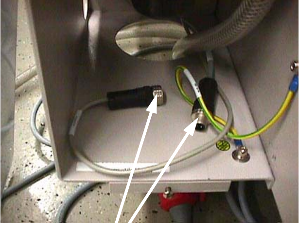
The option is automatically activated with the plug-in contact of the vacuum tooling – solenoid
valve cable (00332746). 2
If this cable is plugged in so that the vacuum tooling is activated, then the width adjustment unit
can no longer move together. 2
2.2.2 Restrictions
The automatic width adjustment unit must have been deactivated. The barcode reader on the in-
put belt, the stopper on the input belt and the vacuum tooling in the handling area must have been
designed exclusively for the customer's wafer boat, which will be acceptance tested by Commis-
sioning in Munich. 2
2.3 Working principle with circuit diagrams
2.3.1 Digital half-bridge circuit
The digital half-bridge circuit is needed to adjust the speed of the input belt. This is necessary so
that the wafer boat moves slowly against the stopper onto the input belt. The digital half-bridge
card should be operated in parameter set 3 by default. 2
2.3.2 Vacuum tooling control (part no.: 00331378-01)
The "Vacuum tooling control“ module performs two functions: 2
– Delayed lowering of the lifting table
– Input belt after-run time
The lifting table is lowered after a delay. This delay ensures that the vacuum has fully dissipated
by the time lowering starts. The input belt after-run time is needed to ensure that the wafer boat is
carried as far as the stopper. 2
2.3.3 Photoelectric switches on the input and center belts
PCB position detection by means of a sonar sensor is not possible due to the built-in vacuum plate
and the stopper, so photoelectric switches are fitted on the input and center belts. 2
Functional description - Special design for the hybrid clamping unit with vacuum check
02/2006 Edition
31
2.3.4 Vacuum check
The placement process does not start unless three conditions are fulfilled: 2
– The vacuum threshold in the Keyence pressure sensor has been reached (approx. –650
mbar).
– The lifting table is "up".
– The center belt sensor is covered (photoelectric switch).
2.3.5 Deactivating the width adjustment unit
The conveyor side walls are prevented from moving together when the vacuum tooling / solenoid
valve connecting cable is plugged in. 2
2
2.3.6 Opticon barcode reader
Only the PCB barcode of the first substrate in the wafer boat has to be read. To guarantee this an
additional stopper is installed on the input belt. 2
2
2
2
2
Joining the connectors prevents the
conveyor side walls moving together.