Hybridklemmung mit Vakuumabfrage (Funktionsbeschreibung).pdf - 第47页
Functional description - Special design for t he hybrid clamping unit with vacuum check 02/2006 Edition 47 2.7 Programming the Opticon barcode reader Connect the power supply to the bar code reader . The barcode should n…
Functional description - Special design for the hybrid clamping unit with vacuum check
02/2006 Edition
46
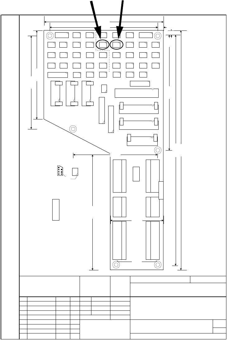
2.6.4 Installing the photoelectric switches
The photoelectric switches are plugged in at X34/X36 on the conversion board. 2
2
1.
3.
1.
10.04.97
10.04.97
10.04.97 Tu.
Tu.
Tu.
02.07.1996
02.07.1996
00325581-030101MD4
SIEMENS
Aktiengesellschaft
AUT 5 EBS 8
Date
Author
Check.
Stand.
Name
File name:
Stat.
Modified
Date
Name
(Material number)
Format A4
Mat.-No.: FS PS DS S/F
Sheet
Scale
Weitergabe sowie Vervielfältigung dieser Unterlage, Verwertung und Mitteilung
ihres Inhaltes nicht gestattet, soweit nicht ausdrücklich zugestanden.
Zuwiderhandlungen verpflichten zu Schadenersatz. Alle Rechte für den Fall
der Patenterteilung oder GM-Eintragung vorbehalten.
Copying of this document, and giving it to others and the use or communication
of the contents thereof, are forbidden without express authority. Offenders are
liable to the payment of damages. All rights are reserved in the event of the
grant of a patent or the registration of the utility model or design.
X12 20 pol AMP
X13 20pol AMP
270 mm
130 mm
135mm
100 mm
60 mm
48mm
258 mm
129 mm
6 mm
6 mm123 mm
104 mm
94 mm
Pin 1
Key 1
Key 1
Key 1
Key 2
Key 2
Key 2
X45
5
X16
10
5
X24
5
X22
X20
1
X18
3
X42
5
X30
1
X48
4
X44
X38
1
X32
4
X26 X28
5
X36
4
X34
1
X40
4
X46
4
X6
BK-Mod 30pol
X8
BK-Mod 26pol
X10
BK-Mod 26pol
X7
BK-Mod 20pol
X5
BK-Mod 14pol
X3
BK-Mod 14pol
X4
BK-Mod 14pol
J1
X47 X45
5
X41 X43
4
X19
3
X21
1
X23
X49
5
X35
1
X37
4
X39
1
X33
1
X27
X31
4
X29
1
X17
9
25
5
X2
Combicon 7pol.
.1
X1
Combicon 7pol
1.
X14
Combi. 4pol
.1
X15
Combi. 4pol
1.
X11
Combicon 8pol
1.
X9
Combicon 8pol.
.1
00325581.M31
1/1
Siemens AUT 5
00325581-01
B
A
X57
2 und 13
X56
1 + 14
X55
5
X53
1
X51
4
X50
1
X52
5
X54
1
14
15
Siplace 80S20/F4 SMD placement system
Conversion board, PCB conveyor
Function status
Product status
Document. status
6 Bohrungen D=4,5 mm
Toleranzen +/- 0,1mm
Plugs X12, X13, X16 - X49
viewed from top
Plug designation
and coding (pin no.)
Combicon plug coding
Codierreiter CR-MSTB Item no.: 1734401
J1 Jumper on pins 1-2
A Inscription label
B Inspection label
Photo-electric switch middle conveyor X36
Photo-electric switch input conveyorX34

Functional description - Special design for the hybrid clamping unit with vacuum check
02/2006 Edition
47
2.7 Programming the Opticon barcode reader
Connect the power supply to the barcode reader. The barcode should now be active. If the scan-
ner diodes do not light up, the trigger has already been programmed. This can be bypassed by
jumpering PIN 7 (Ground) and PIN 11 (Trigger) in the connector. 2
Program each page as shown below: First SET - Barcode, then Parameter - Barcode and finally
END - Barcode. 2
2
2
2
Important:First plug in the barcode reader and then plug in the power plug. 2
2
2
2
2.8 Settings
2.8.1 Setting the speed of the conveyor belts
The digital half-bridge card in the conveyor control should be programmed using the programming
software (part no.:00332468-xx) at 4 parameter sets (or it is preprogrammed by Munich). This will
gradually reduce the input speed in 4 stages, from OffOff (fast) to OnOn (slow). 2
2
2
2
2
2
Order
Page Parameter Comment
1 U11 U2 RS232
2 U27 K6 9600 baud
3 U29 L1 / L2 / L5 8 data bits / no parity / 1 stop bit
4 U60 A2 Code 39 only
5 U108 + U128 RY 1B Prefix all codes +STx
6 U111 + U129 RZ 1M 1J Suffix all codes +CR+LF
7 U135 SØ Single read
8 U143 Y6 6 second read time
9
U135 S8 Enable trigger
!Always program last!
The trigger is then active!

Functional description - Special design for the hybrid clamping unit with vacuum check
02/2006 Edition
48
Parameters for setting the digital half-bridge card 2
2
Parameter set
0
1 OFF
2 OFF
1
1 ON
2 OFF
2
1 OFF
2 ON
3
1 OFF
2 ON
Page 1
CB 1 Final value slow 100 100 100 100
CB 1 Final value fast 255 255 255 255
CB 1 Start-up ramp 0 0 0 0
CB 1 Braking ramp 0 0 0 0
CB 1 Max. braking distance (mm) 0 0 0 0
OB 1 Final value slow 255 255 255 255
OB 1 Final value fast 255 255 255 255
OB 1 Start-up ramp 0 0 0 0
OB 1 Braking ramp 0 0 0 0
OB 1 Max. braking distance (mm) 0 0 0 0
Page 2
IB 1 Final value slow 100 100 100 100
IB 1 Final value fast 255 220 180 150
IB 1 Start-up ramp 0 0 0 0
IB 1 Braking ramp 0 0 0 0
IB 1 Max. braking distance (mm) 0 0 0 0
CB 2 Final value slow 100 100 100 100
CB 2 Final value fast 255 255 255 255
CB 2 Start-up ramp 0 0 0 0
CB 2 Braking ramp 0 0 0 0
CB 2 Max. braking distance (mm) 0 0 0 0
Page 3
OB 2 Final value slow 255 255 255 255
OB 2 Final value fast 255 255 255 255
OB 2 Start-up ramp 0 0 0 0
OB 2 Braking ramp 0 0 0 0
OB 2 Max. braking distance (mm) 0 0 0 0
IB 2 Final value slow 100 100 100 100
IB 2 Final value fast 255 220 180 150
IB 2 Start-up ramp 0 0 0 0
IB 2 Braking ramp 0 0 0 0
IB 2 Max. braking distance (mm) 0 0 0 0