Hybridklemmung mit Vakuumabfrage (Funktionsbeschreibung).pdf - 第48页
F unctional description - Special design for the hybrid clamping unit with vacuum check 02/2006 Edition 48 Parameters for setting the digit al half-bridge card 2 2 Parameter set 0 1 OFF 2 OFF 1 1 ON 2 OFF 2 1 OFF 2 ON 3 …

Functional description - Special design for the hybrid clamping unit with vacuum check
02/2006 Edition
47
2.7 Programming the Opticon barcode reader
Connect the power supply to the barcode reader. The barcode should now be active. If the scan-
ner diodes do not light up, the trigger has already been programmed. This can be bypassed by
jumpering PIN 7 (Ground) and PIN 11 (Trigger) in the connector. 2
Program each page as shown below: First SET - Barcode, then Parameter - Barcode and finally
END - Barcode. 2
2
2
2
Important:First plug in the barcode reader and then plug in the power plug. 2
2
2
2
2.8 Settings
2.8.1 Setting the speed of the conveyor belts
The digital half-bridge card in the conveyor control should be programmed using the programming
software (part no.:00332468-xx) at 4 parameter sets (or it is preprogrammed by Munich). This will
gradually reduce the input speed in 4 stages, from OffOff (fast) to OnOn (slow). 2
2
2
2
2
2
Order
Page Parameter Comment
1 U11 U2 RS232
2 U27 K6 9600 baud
3 U29 L1 / L2 / L5 8 data bits / no parity / 1 stop bit
4 U60 A2 Code 39 only
5 U108 + U128 RY 1B Prefix all codes +STx
6 U111 + U129 RZ 1M 1J Suffix all codes +CR+LF
7 U135 SØ Single read
8 U143 Y6 6 second read time
9
U135 S8 Enable trigger
!Always program last!
The trigger is then active!

Functional description - Special design for the hybrid clamping unit with vacuum check
02/2006 Edition
48
Parameters for setting the digital half-bridge card 2
2
Parameter set
0
1 OFF
2 OFF
1
1 ON
2 OFF
2
1 OFF
2 ON
3
1 OFF
2 ON
Page 1
CB 1 Final value slow 100 100 100 100
CB 1 Final value fast 255 255 255 255
CB 1 Start-up ramp 0 0 0 0
CB 1 Braking ramp 0 0 0 0
CB 1 Max. braking distance (mm) 0 0 0 0
OB 1 Final value slow 255 255 255 255
OB 1 Final value fast 255 255 255 255
OB 1 Start-up ramp 0 0 0 0
OB 1 Braking ramp 0 0 0 0
OB 1 Max. braking distance (mm) 0 0 0 0
Page 2
IB 1 Final value slow 100 100 100 100
IB 1 Final value fast 255 220 180 150
IB 1 Start-up ramp 0 0 0 0
IB 1 Braking ramp 0 0 0 0
IB 1 Max. braking distance (mm) 0 0 0 0
CB 2 Final value slow 100 100 100 100
CB 2 Final value fast 255 255 255 255
CB 2 Start-up ramp 0 0 0 0
CB 2 Braking ramp 0 0 0 0
CB 2 Max. braking distance (mm) 0 0 0 0
Page 3
OB 2 Final value slow 255 255 255 255
OB 2 Final value fast 255 255 255 255
OB 2 Start-up ramp 0 0 0 0
OB 2 Braking ramp 0 0 0 0
OB 2 Max. braking distance (mm) 0 0 0 0
IB 2 Final value slow 100 100 100 100
IB 2 Final value fast 255 220 180 150
IB 2 Start-up ramp 0 0 0 0
IB 2 Braking ramp 0 0 0 0
IB 2 Max. braking distance (mm) 0 0 0 0
Functional description - Special design for the hybrid clamping unit with vacuum check
02/2006 Edition
49
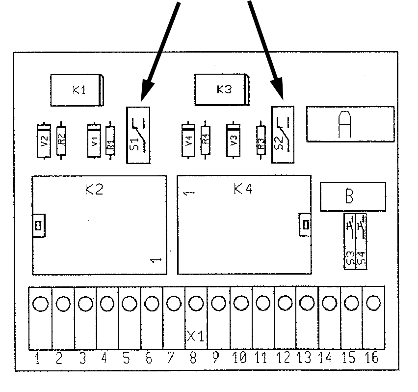
2.8.2 Setting the lifting table and input belt delay
These delays are set via the vacuum tooling control: 2
K2 determines the lifting table delay (setting: approx. 0.5 sec).
The vacuum must have dissipated before the lifting table can be lowered. 2
K4 determines the input belt after-run time (setting: approx. 0.7 sec). The after-run time ensures
that the PCB reaches the stopper position. 2
It is set on the module using potentiometers. 2
2
Lifting table
approx. 0.5 sec
Input conveyor
approx. 0.7 sec
Switch in position 2:
Delay relay active
2
2
1
1