TSR2000-Series-Hardware-User-Guide-V1.pdf - 第11页
11 3.1.4 T esting the Interface Connections TS250, TS350, TS500R an d TS920 with TSR- VCABLE and TSR-DJETCABLE – 1 Dispense Head in U se TS250, TS350 and TS500 R with TSR- VCABLE – Multiple Dispens e Heads in U se The TS…
10
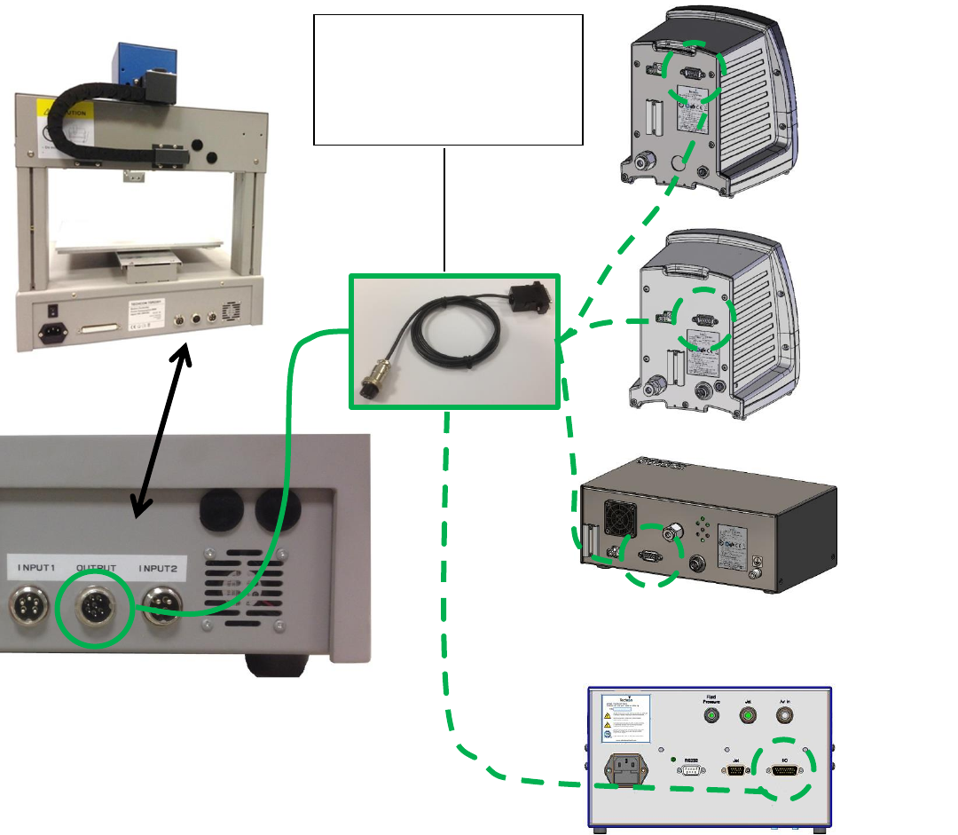
3.1.1 How to Connect a (TS250 or TS350) Syringe Dispenser with Interface Cable
Take the supplied TSR-VCABLE and connect the round female connector to the male “OUTPUT” connector on
the rear of the robot. Take the opposite end and connect the female 9 pin connector to the DB9 connector on the
rear of the TS250 or TS350 Series controllers.
3.1.2 How to Connect a (TS500R) Valve Controller with Interface Cable
Take the supplied TSR-VCABLE and connect the round female connector to the male “OUTPUT” connector on
the rear of the robot. Take the opposite end and connect the female 9 pin connector to the DB9 connector on the
rear of the TS500R controller.
3.1.3 How to Connect a (TS920) Jet Valve Controller with Interface Cable
Take the optional TSR-DJETCABLE and connect the round female connector to the male “OUTPUT” connector
on the rear of the robot. Take the opposite end and connect the male 26 pin connector to the rear of the TS920, jet
valve controller, marked I/O.
444
TS500R
Controller
TS920 Jet
Controller
TS350
Dispenser
TS250
Dispenser
TSR-VCABLE – to connect to
TS250, TS350 and TS500R.
TSR-DJETCABLE – to
connect to TS920 jet controller.
11
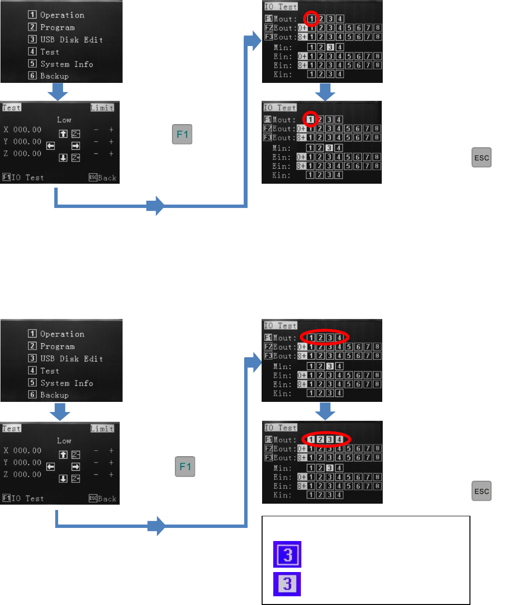
3.1.4 Testing the Interface Connections
TS250, TS350, TS500R and TS920 with TSR-VCABLE and TSR-DJETCABLE – 1 Dispense Head in Use
TS250, TS350 and TS500R with TSR-VCABLE – Multiple Dispense Heads in Use
The TSR2000 Series robot is capable of operating up to 4 dispensers/controllers during a program. An optional cable
is made available for this function. Please contact Techcon if this specialty cable is required. Follow the instructions,
below, to test the other available outputs.
Press 4
Press
Press 4
Press
By pressing button 1, the
controller will activate. If
the system is complete and
under pressure, fluid will
exit out of the dispense
outlet.
Press 1 to turn off output.
To go back to main screen,
press
multiple times.
Press 1 through 4 to turn
off outputs.
To go back to main
screen, press
multiple times
By pressing buttons 1
through 4, the dispensers/
controllers will activate. If
the systems are complete
and under pressure, fluid
will exit out of the
dispense outlets.
Legend:
Output not activated
Output activated
12
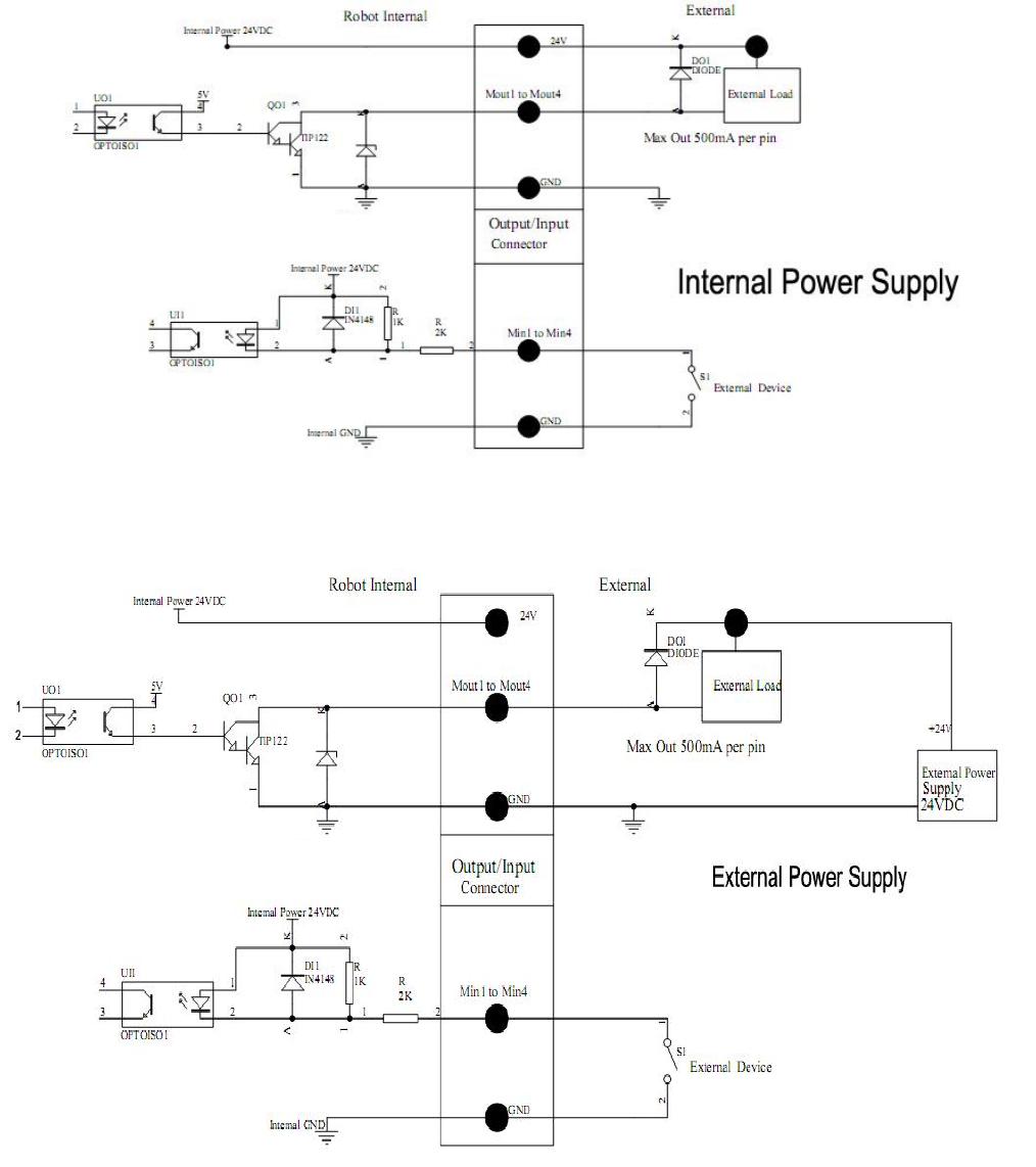
3.2 I/O Socket Instruction
3.2.1 Circuit Diagram of I/O Socket
Inside
Inside