TSR2000-Series-Hardware-User-Guide-V1.pdf - 第21页
21 4. OFF-LINE OPER ATION INT ERFAC E Caution: when connecting the teaching pendant w i th th e m ain unit, the but tons on the fron t p anel of the unit are invalid e xcept ST AR T/P AUSE , FEED & ORG . 4.1 Off-Line…

20
Function of Output
Function Instruction
--
Not have function.
Nozzle 1
Once the nozzle 1 comes to run the program, the output is in conducting state, or else
not.
Nozzle 2
Once the nozzle 2 comes to run the program, the output is in conducting state, or else
not.
Nozzle 3
Once the nozzle 3 comes to run the program, the output is in conducting state, or else
not.
Nozzle 4
Once the nozzle 4 comes to run the program, the output is in conducting state, or else
not.
Ready flag
When the unit comes into the normal ready state, the output is in conducting state,
namely, once receiving the “START” signal, it comes to run. And it closes the output
after running.
Alarm flag
When set the mode as alarming, once it detects the abnormal state, the output is in
conducting state, or else not.
Working flag
When the unit comes into the working state, the output is in conducting state, or else
not.
WorkEnd flag
After t finishing the process, the output is keeping in conducting state 200ms, or else
not.
Cylinder
Once the unit comes to run the cylinder process, the output is in conducting state, control
cylinder motion, or else not.
Clean output
Once the unit comes to run the clean process, the output is in conducting state, do the
clean (blowing or revolving brush), or else not.
Note:
⚫ The function settings of input & output cannot be accessed by the operator. It can only be operated by the
manufacturer.
⚫ Will not give advanced information if some functions are changed.
3.5 Operation For First Time Use
If using the unit for the first time, the operator should test the basic functionalities.
Step 1: Install and Test
Before using, the operator should properly install and connect the system. The operator should test the basic
functionalities of the system with the ‘Test’ function on the teaching pendant. Test should include if there are any
problems with the axis movements towards positive or negative directions.
Step 2: Parameters Setting
Correctly set the global parameters and other parameters being used in the process.
Remark: Failure to properly set the parameters will cause difficulties in using the system.
Step 3: Teaching Program
Program a profile with teaching pendant. Refer to the instruction manual of the teaching pendant.
Step 4: Origin Calibration & Setting the Parameters of the Teaching Pendant
1. Origin calibration: The operator should adjust the start point when a teaching file is created for the first time.
2. Set file parameters.
Step 5: Download & Process
1. Download: refer to instruction manual of the teaching pendant “Teaching File Download”.
2. Process: refer to instruction manual of the teaching pendant “File Processing”.

21
4. OFF-LINE OPERATION INTERFACE
Caution: when connecting the teaching pendant with the main unit, the buttons on the front panel of the
unit are invalid except START/PAUSE, FEED & ORG.
4.1 Off-Line Initialization
1. When the system is turned on without connecting to the teaching pendant, the LCD will enter initialization
interface automatically (Refer to Fig.4-1).
LOADING...
>>>-----------------
2. After 5 seconds, the initialization is complete and the system enters into the file processing interface.
4.2 Off- Line File Processing Interface
1. After initialization, the system will enter the “Processing Interface”. This interface is frequently used when not
connected to the teaching pendant. Enter into the other settings interface through the processing interface.
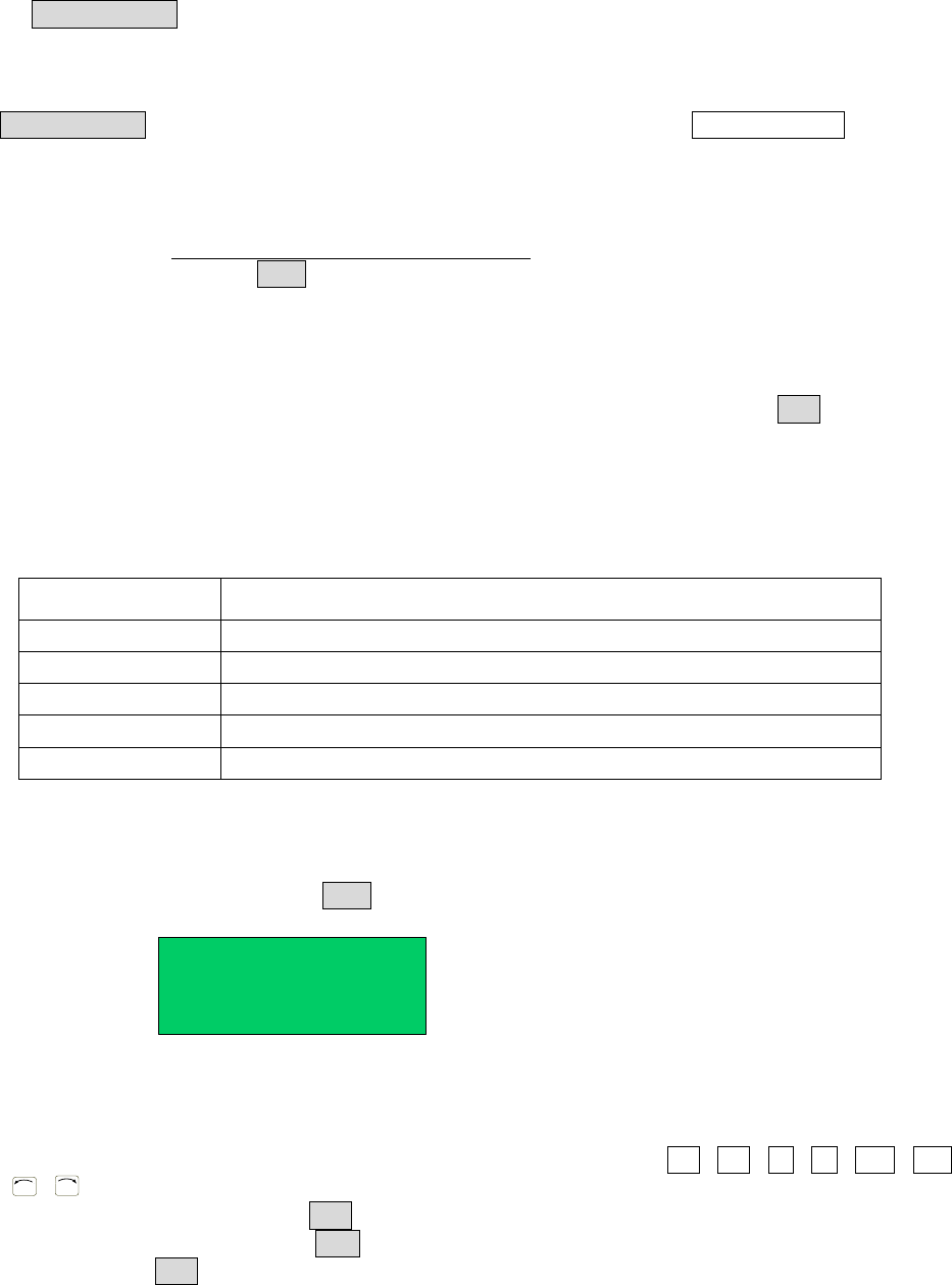
2. In the circulating processing interface, the LCD will display information such as “already processed times /set
processing times”.
All information showing on the LCD display are as follows:
SJ001
N:0003
01/30
STOP
File Name
Processing State
File No. File Count
Processing Times
SJ001
0001/0002
01/30
STOP
Set Times about
the Loop-Work
Current
Processing Times
3. Enter the “Origin calibration Interface” by pressing the “HOME” button.
4. Enter the “Testing Interface” by pressing the “ESC” button.
5. Enter the “Loop-work Processing Work” by pressing the “LOOP” button.
6. In any sub-menu, return to the “File Processing Interface” by pressing the “ESC” button, but the set parameters
will not be saved.
7. In any submenu, press the “ENT” button to save the set parameters and then return to the “Processing Interface”.
4.2.1 Select Processing File
1. Select the processing file with the six directional buttons.
2. “ \ \ Z ” buttons can be used to select previous file, and “ \ \ Z ” buttons can be used to
select the next file.
Fig. 4-2: Processing Interface of non Loop-work
Fig. 4-3: Processing Interface of Loop-work
Fig. 4-1: Initialization Interface
22
4.2.2 File Process
Press the “START/PAUSE” button to begin processing the selected file.
This button also can used to pause a file processing and then continue a file processing.
4.2.3 Stop the File Processing
Press “START/PAUSE” button or Emergency Switch to pause the processing file. START/PAUSE: only pauses
file processing, and the file state changes from “WORK” to “PAUSE”. If pressed again, the system will continue
the paused processing file and the file state changes to “WORK”.
Emergency Switch: Stops file processing and cuts off the power supply of the driver, the LCD displays
“EMERGENCY STOP PLEASE RESET”. Turn the emergency switch clockwise to reset.
Press the “ORG” button to make the tip return to the zero point. After that, the emergency
switch can be run again.
4.2.4 File Processing Count And State
1. At the lower left corner of processing interface the processing times are displayed. Press “SHF” button to clear
the digit to 0.
2. At the lower right corner of processing interface, the file processing state is displayed. The processing state is
changing with the processing course. The file processing state shown in the table below:
Table 4-1: File Processing State
Work State
Remark
RESET
The system is resetting.
STOP
The process has been stopped.
WORK
Processing.
PAUSE
The process has been paused.
WAIT
Waiting time for hanging a work-piece during the loop-work process.
4.3 Off- Line Origin Calibration Interface
1. During the file processing, the deviation can be calibrated between the processing file and the real route by the
origin calibration.
2. At the file processing interface, press “ORG” button to go to the origin calibration interface.
X 033.3
Z 00000
Y 067.5
R 00000
Fig. 4-4: Origin Calibration Interface
X/Y/Z/R displays the tips current position. “MID” means the current processing speed is in the middle.
3. Orientation: the nozzle will move to the origin automatically when coming into the origin calibration interface.
4. Adjusting the tips position: After orientation, press the arrow buttons “ / / / / Z / Z /
R
/
R
” to adjust the tips position.
5. Adjust the point’s speed: click the “SHF” button to change the point speed, MID-LOW-HI.
6. Calibration: after calibration, press “ENT” button to save the origin change and return to the file processing
interface. If press “ESC” button, it will not save the calibration result, and directly return file processing
interface.