TSR2000-Series-Hardware-User-Guide-V1.pdf - 第13页
13 3.2.2 Four Pi n Socket “P in Out” - the following lis t describes the pin function o f the four -pin socket. Four -pin socket Pin No. Pin name Instruction of pin s Application 1 Min4 Main signal inp ut 4 Now it’ s use…
12
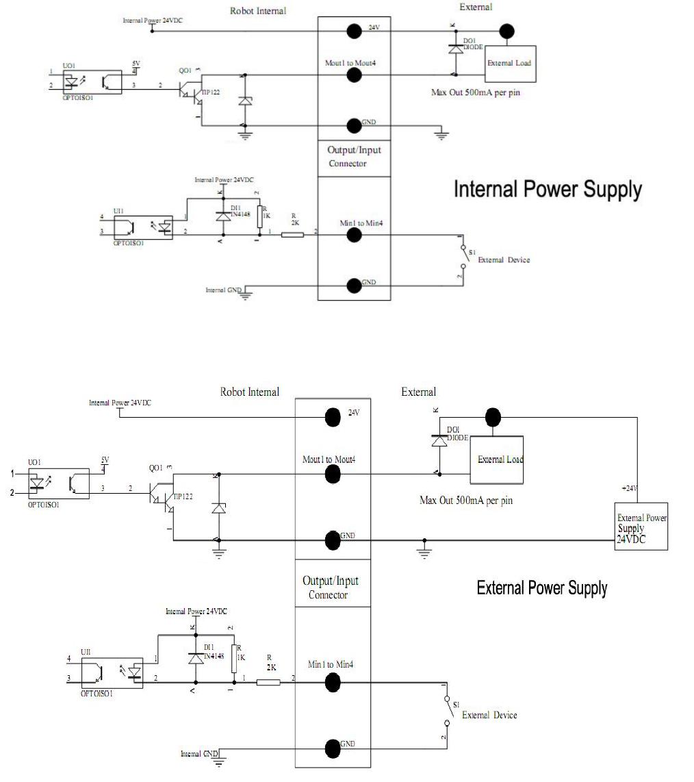
3.2 I/O Socket Instruction
3.2.1 Circuit Diagram of I/O Socket
Inside
Inside
13
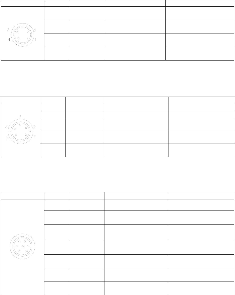
3.2.2 Four Pin Socket “Pin Out” - the following list describes the pin function of the four-pin socket.
Four-pin socket
Pin No.
Pin name
Instruction of pins
Application
1
Min4
Main signal input 4
Now it’s used to connect to
“START/STOP” switch.
2
GND
Ground of power supply
3
Min1
Main signal inputting 1
Now used to reset (ORG) signal
4
Min2
Main signal inputting 2
Now used to connect emergency
stop switch
Note: *If a special function is required, the input and output signal can be set again.
3.2.3 Five Pin Socket “Pin Out”- the following list describes the pin function of the five-pin socket. The socket
can connect with a photo-electricity switch etc.
Five-pin socket
Pin No.
Pin name
Instruction of pins
Application
1
24VDC
“+” power supply
Output signal
2
GND
Ground of power supply
3
Min3
Main signal inputting 3
connect to sensor, such as
photoelectric switch
4
Ein13
External input 13
Used as alarm when
lacking fluid, etc.
5
Ein14
External input 14
Used as alarm when
lacking fluid, etc.
Note: *If a special function is required, the input and output signal can be set again.
3.2.4 Seven Pin Socket “Pin Out” - the following list describes the pins function of the seven-pin socket. By the
socket, it can control the external device.
Seven-pin socket
Pin No.
Pin name
Instruction of pins
Application
1
2
3
4
5
6
7
1
24V
“+” power supply
Output signal
2
GND
Ground of power supply
3
Mout1
Main signal output 1, the
current is less than 0.5A
Feeding signal
4
Mout4
Main signal output 4, the
current is less than 0.5A
Cylinder movement signal
5
Min1
Reset and return to the zero
position
Reset (ORG) signal
6
Mout2
Main signal output 2, the
current is less than 0.5A
Output working state signal
7
Mout5
Main signal output 5, the
current is less than 0.5A
Effective as pulse signal
inputted
Note: *If a special function is required, the input and output signal can be set again.
14
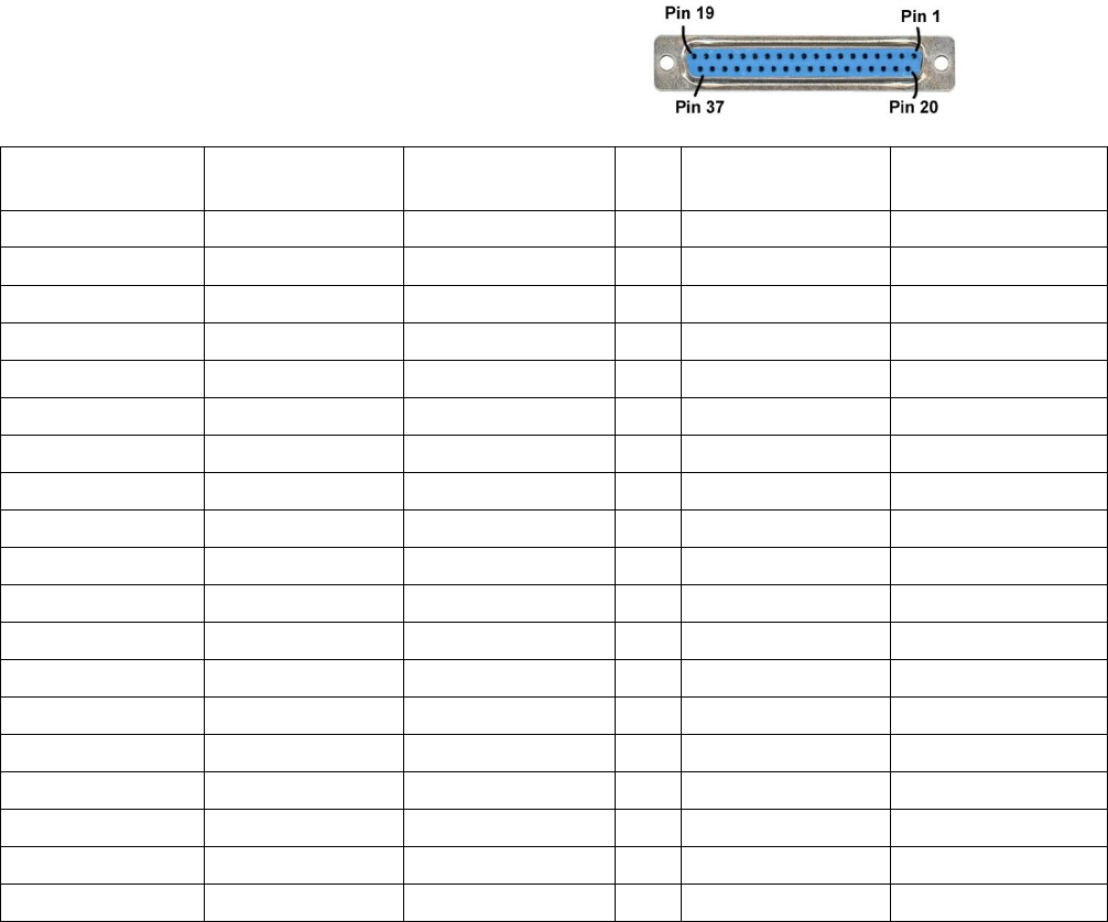
3.3 Instructions For DB37 Socket
Note: The DB37 socket is an optional fitting and must be ordered separately if required.
3.3.1 Pin Instruction of DB37
NO.
Interface
Definition DB37
Corresponding
I/O pins DB37
No.
Interface
Definition DB37
Corresponding
I/O pins DB37
1
GND
P01
20
GND
P20
2
Eout8
P02
21
Ein8
P21
3
Eout7
P03
22
Ein7
P22
4
Eout6
P04
23
Ein6
P23
5
Eout5
P05
24
Ein5
P24
6
Eout4
P06
25
Ein4
P25
7
Eout3
P07
26
Ein3
P26
8
Eout2
P08
27
Ein2
P27
9
Eout1
P09
28
Ein1
P28
10
COM
P10
29
GND
P29
11
GND
P11
30
Ein16
P30
12
Eout16
P12
31
Ein15
P31
13
Eout15
P13
32
Ein14
P32
14
Eout14
P14
33
Ein13
P33
15
Eout13
P15
34
Ein12
P34
16
Eout12
P16
35
Ein11
P35
17
Eout11
P17
36
Ein10
P36
18
Eout10
P18
37
Ein9
P37
19
Eout9
P19
(socket of DB37)