TSR2000-Series-Hardware-User-Guide-V1.pdf - 第9页
9 2.5 Course of the File Pr ocess ing T o complete a process f ile t here needs to be three steps: pr ogram-adjust-pr oces s . For detailed operation refer t o the “operation man ual of th e teaching pendan t”. Program :…
8
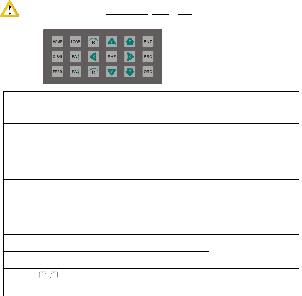
2.4 Instructions about the Keypad - the keypad, on the robot face, can be used when the teaching pendant is
disconnected.
Caution: when connecting the teaching pendant with the main unit (robot), the buttons on the front panel
of the unit are invalid except START/PAUSE, FEED & ORG. If fitting with throttling valve to control
the movement of glue tube, the button FA↑ & FA↓ can be used.
Button
Function Description
X / X / Y / Y / Z / Z
Control the axis’ coordinate
【HOME】
Move the tip to the origin of the processing file, this can be set.
【SHF】
Switch point processing speed, 3 level: low, middle, high
【ENT】
Save the set parameters
【ORG】
Reset, move the tip to the zero point (0,0,0)
【LOOP】
Set the loop operating parameters
【ESC】
1. Return to file processing interface but not save the set parameters.
2. Enter into the testing interface, test the axis’s function
【FEED】
Control dispensing
【FA】
N/A
N/A
【FA】
N/A
R
/
R
Control the R axis’ coordinate
* With R axis type
【START/PAUSE】
Start or pause the processing file.
For Further functions and detailed use of the
buttons refer to the chapter 4 “off-line
operation instruction”.
9
2.5 Course of the File Processing
To complete a process file there needs to be three steps: program-adjust-process. For detailed operation refer to
the “operation manual of the teaching pendant”.
Program: The method of teaching a program.
Adjust: Adjusting the programming file, such as origin calibration, slant array, height adjusts, file
parameters adjust (including speed, acceleration, delay time, distance etc.)
Process: Download the program file to the system, from the teaching pendant.
The program is now complete and can be initiated.
3. SETUP AND CONNECTION
3.1 Setup
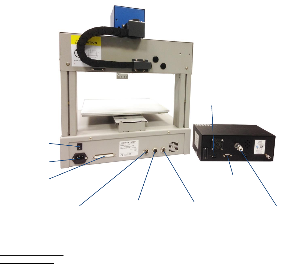
Connecting air tubing: directly insert the air tube into the air connector, on the back of the controller.
Removing air tube: press down the connector head and then pull out the air tube, from the controller.
DB9 – connect with
7-pin socket
Power switch
Power socket
INPUT 2
4-pin socket.
Connect to keybox
OUPUT
7-pin socket. Connect
with controller (DB9)
Air inlet
Power socket
DB37 - Additional Outputs
INPUT 1
5-pin socket. Connect to
safety cover, photoelectric
switch or low fluid switch.
10
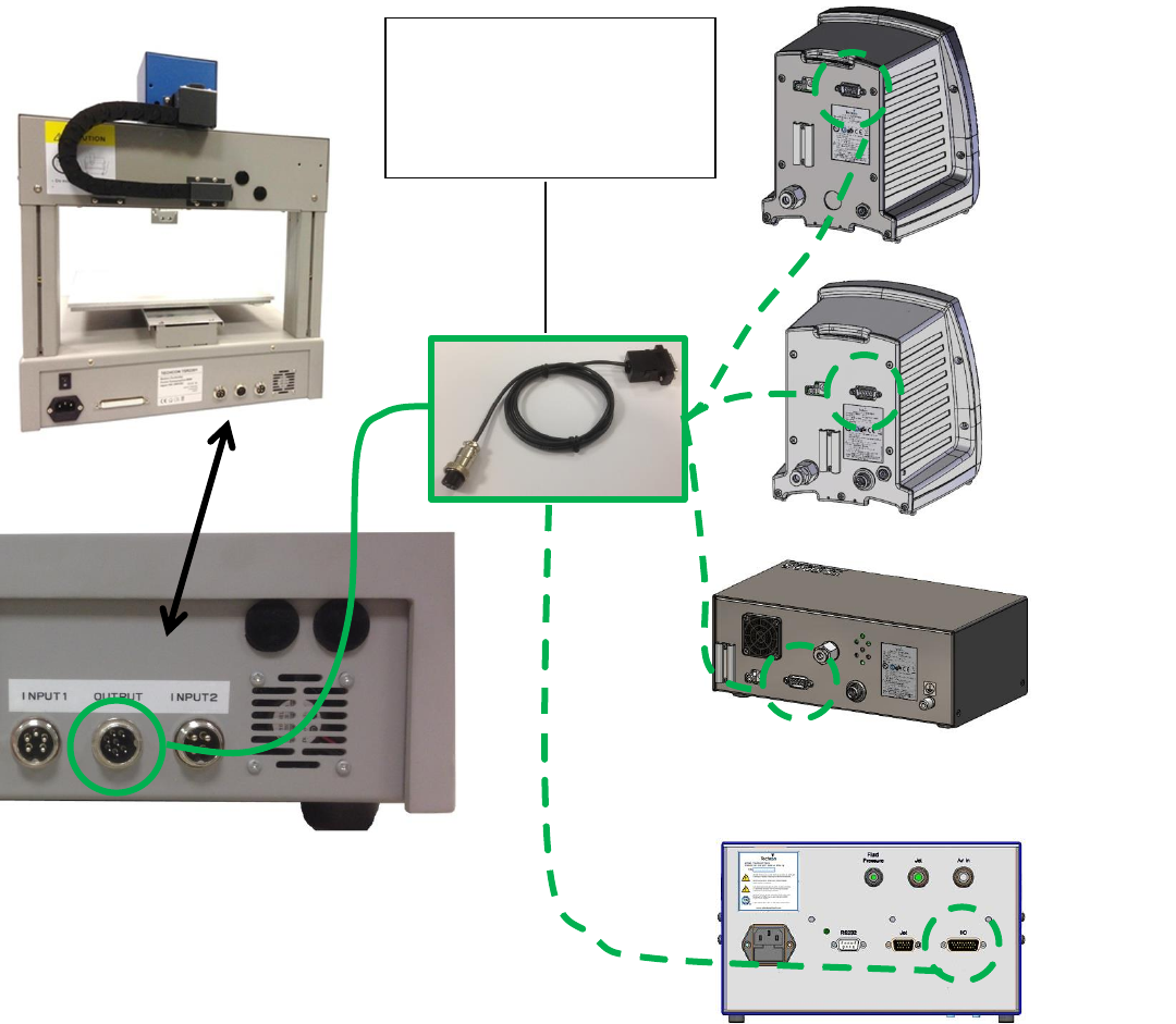
3.1.1 How to Connect a (TS250 or TS350) Syringe Dispenser with Interface Cable
Take the supplied TSR-VCABLE and connect the round female connector to the male “OUTPUT” connector on
the rear of the robot. Take the opposite end and connect the female 9 pin connector to the DB9 connector on the
rear of the TS250 or TS350 Series controllers.
3.1.2 How to Connect a (TS500R) Valve Controller with Interface Cable
Take the supplied TSR-VCABLE and connect the round female connector to the male “OUTPUT” connector on
the rear of the robot. Take the opposite end and connect the female 9 pin connector to the DB9 connector on the
rear of the TS500R controller.
3.1.3 How to Connect a (TS920) Jet Valve Controller with Interface Cable
Take the optional TSR-DJETCABLE and connect the round female connector to the male “OUTPUT” connector
on the rear of the robot. Take the opposite end and connect the male 26 pin connector to the rear of the TS920, jet
valve controller, marked I/O.
444
TS500R
Controller
TS920 Jet
Controller
TS350
Dispenser
TS250
Dispenser
TSR-VCABLE – to connect to
TS250, TS350 and TS500R.
TSR-DJETCABLE – to
connect to TS920 jet controller.