TSR2000-Series-Hardware-User-Guide-V1.pdf - 第18页
18 2. In the “Output C onfig 2” display w indow , the input interface can b e set: Mout1~Mout 4, Eout09~Eo ut16. Output Interface Optional Function Mout1~Mout4 -- , No zzle 1, Nozzle 2, Nozzle 3, Noz zle 4, W orking F la…

17
3.4.1 IO Function Definition
1. In the “Input Config 2” displaying window, it can set the input interface: Min1~Min4 & Ein1-8 & Ein 09~Ein16.
Input Interface
Optional Function
Min1
--, Shortcut1, Origin BTN, Test input-L, Test input-H
Min2
--, Shortcut 2, Stop BTN, Test input-L, Test input-H
Min3
--, Shortcut 3, Start BTN, Test input-L, Test input-H, Lack fault, Block fault, Temp fault,
Temp\Feed fault, Upper CS, Nether CS
Min4
--, Shortcut 4, Foot BTN, Test input-L, Test input-H
Ein1~Ein8
--, Shortcut 5-259
Ein09
--, Origin BTN, Stop BTN, Start BTN, Foot BTN, Test input-L, Test input-H, Adj X-Limit,
Shortcut 260, Upper CS, Nether CS
Ein10
--, Origin BTN, Stop BTN, Start BTN, Foot BTN, Test input-L, Test input-H, Adj X-Limit,
Shortcut 261, Upper CS, Nether CS
Ein11
--, Origin BTN, Stop BTN, Start BTN, Foot BTN, Test input-L, Test input-H, Adj X-Limit,
Shortcut 262, Upper CS, Nether CS
Ein12
--, Origin BTN, Stop BTN, Start BTN, Foot BTN, Test input-L, Test input-H, Shortcut 263,
Lack fault, Block fault, Temp fault, Temp\Feed fault, Upper CS, Nether CS
Ein13
--, Origin BTN, Stop BTN, Start BTN, Foot BTN, Test input-L, Test input-H, Shortcut 264,
Lack fault, Block fault, Temp fault, Temp\Feed fault, Upper CS, Nether CS
Ein14
--, Origin BTN, Stop BTN, Start BTN, Foot BTN, Test input-L, Test input-H, Shortcut 265,
Lack fault, Block fault, Temp fault, Temp\Feed fault, Upper CS, Nether CS
Ein15
--, Origin BTN, Stop BTN, Start BTN, Foot BTN, Test input-L, Test input-H, Shortcut 266,
Lack fault, Block fault, Temp fault, Temp\Feed fault, Upper CS, Nether CS
Ein16
--, Origin BTN, Stop BTN, Start BTN, Foot BTN, Test input-L, Test input-H, Shortcut 267,
Lack fault, Block fault, Temp fault, Temp\Feed fault, Upper CS, Nether CS
18
2. In the “Output Config 2” display window, the input interface can be set: Mout1~Mout4, Eout09~Eout16.
Output Interface
Optional Function
Mout1~Mout4
--, Nozzle 1, Nozzle 2, Nozzle 3, Nozzle 4, Working Flag, WorkEnd Flag, Cylinder, Clean
Output
Eout09~Eout16
--, Ready Flag, Alarm Flag, Working Flag, WorkEnd Flag, Cylinder, Clean Output
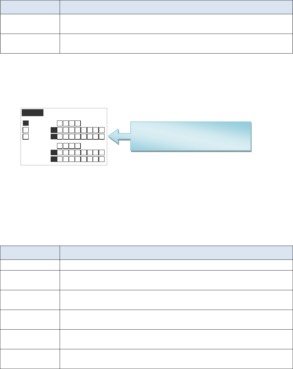
3. In the teaching pendant, “Eout09~Eout16” are corresponding to the “Eout8+ (0~8)” at the “IO Test” and
“Output (point)” displaying window.
IO Test
Mout :
F1
32 41
0+
32 41 76 85
32 4 76 85
32 4 76 85
32 41
8+
1
Eout :
F2
Eout :
F3
Min :
Ein :
32 4 76 85
Ein :
0+
8+
1
1
Namely, “Eout8+ 1” is the output interface “Eou09”. “Eout8+ 2” is the output interface “Eou10”. “Eout8+ 3” is
the output interface “Eou11”, etc.
3.4.2 IO Function Instruction
Function of Input
Function Instruction
--
N/A.
Origin BTN
Input the reset signal into the unit by corresponding signal pin, and the unit will run the
reset (ORG) operation.
Stop BTN
Input the stop signal into the unit by corresponding signal pin, and the unit stops the
current operation.
Start BTN
Input the start signal into the unit by corresponding signal pin, and the unit starts to work
or pauses the current work.
Foot BTN
Input the foot switch signal into the unit by corresponding signal pin and the unit runs the
foot switch operation and the function is similar with the “Start BTN”.
Test input-L
Input the signal “breakover ground” into the unit by corresponding signal pin and the unit
comes into the testing state (cannot move and can only be programmed).
Mout/Eout/Min/Ein is corresponding to
the “metal socket” at the back of robot.
Can be test before operation.

19
Test output-H
Input the signal “not breakover ground” into the unit by corresponding signal pin and the
unit comes into the testing state (cannot move and can only be programmed).
Lack fault
Input the signal “lack fault” into the unit by corresponding signal pin and the unit comes
into the process, such as stop working, alarming etc..
Block fault
Input the signal “block fault” into the unit by corresponding signal pin and the unit comes
into the process, such as stop working, alarming etc..
Temp fault
Input the signal “temp fault” into the unit by corresponding signal pin and the unit comes
into the process, such as stop working, alarming etc..
Temp/Feed fault
Input the signal “temp/feed fault” into the unit by corresponding signal pin and the unit
comes into the process, such as stop working, alarming etc..
Upper CS
Input the signal “cylinder up sensor (in retraction state)” into the unit by corresponding
signal pin and the unit judges the position of cylinder whether in retraction state.
Nether CS
Input the signal “cylinder down sensor (in reaching state)” into the unit by corresponding
signal pin and the unit judges the position of cylinder whether in reaching state.
Adj X-Limit
Adj Y-Limit
Adj Z-Limit
It is effective only for the soldering robot and only when connecting with “9036 tip
calibration device”. “Adj X-Limit” is corresponding to the “Ein09”. Input the signal by
“Ein09” to calibrate the X-axis of tip. “Adj Y-Limit” is corresponding to the “Ein10”.
Input the signal by “Ein10” to calibrate the Y-axis of tip. “Adj Z-Limit” is corresponding
to the “Ein11”. Input the signal by “Ein11” to calibrate the Z-axis of tip. (Note: only
calibrating X/Y/Z at the same time, it can calibrate the tip’s position.)
Shortcut
It is corresponding to the shortcut of processing file. The shortcut can be set in the “File
Name” display window of teaching pendant. It can be used do find the required processing
files quickly.
Shortcut1
Min1
Shortcut 2
Min2
Shortcut 3
Min3
Shortcut 4
Min4
Shortcut 5~259
It is corresponding to the “Ein1~Ein8”. Namely, the high & low electrical level of
“Ein1~Ein8” can form 255 (1~255) kinds signal. The shortcut (5~259) is the sum of the
electrical level digit add 4.