TSR2000-Series-Hardware-User-Guide-V1.pdf - 第20页
20 Function of Ou tput Function Instruc tion -- Not have function. Nozzle 1 Once the nozzl e 1 comes to run the program, the out put i s in conduc ting state, or else not. Nozzle 2 Once the nozzl e 2 comes to run the pro…

19
Test output-H
Input the signal “not breakover ground” into the unit by corresponding signal pin and the
unit comes into the testing state (cannot move and can only be programmed).
Lack fault
Input the signal “lack fault” into the unit by corresponding signal pin and the unit comes
into the process, such as stop working, alarming etc..
Block fault
Input the signal “block fault” into the unit by corresponding signal pin and the unit comes
into the process, such as stop working, alarming etc..
Temp fault
Input the signal “temp fault” into the unit by corresponding signal pin and the unit comes
into the process, such as stop working, alarming etc..
Temp/Feed fault
Input the signal “temp/feed fault” into the unit by corresponding signal pin and the unit
comes into the process, such as stop working, alarming etc..
Upper CS
Input the signal “cylinder up sensor (in retraction state)” into the unit by corresponding
signal pin and the unit judges the position of cylinder whether in retraction state.
Nether CS
Input the signal “cylinder down sensor (in reaching state)” into the unit by corresponding
signal pin and the unit judges the position of cylinder whether in reaching state.
Adj X-Limit
Adj Y-Limit
Adj Z-Limit
It is effective only for the soldering robot and only when connecting with “9036 tip
calibration device”. “Adj X-Limit” is corresponding to the “Ein09”. Input the signal by
“Ein09” to calibrate the X-axis of tip. “Adj Y-Limit” is corresponding to the “Ein10”.
Input the signal by “Ein10” to calibrate the Y-axis of tip. “Adj Z-Limit” is corresponding
to the “Ein11”. Input the signal by “Ein11” to calibrate the Z-axis of tip. (Note: only
calibrating X/Y/Z at the same time, it can calibrate the tip’s position.)
Shortcut
It is corresponding to the shortcut of processing file. The shortcut can be set in the “File
Name” display window of teaching pendant. It can be used do find the required processing
files quickly.
Shortcut1
Min1
Shortcut 2
Min2
Shortcut 3
Min3
Shortcut 4
Min4
Shortcut 5~259
It is corresponding to the “Ein1~Ein8”. Namely, the high & low electrical level of
“Ein1~Ein8” can form 255 (1~255) kinds signal. The shortcut (5~259) is the sum of the
electrical level digit add 4.

20
Function of Output
Function Instruction
--
Not have function.
Nozzle 1
Once the nozzle 1 comes to run the program, the output is in conducting state, or else
not.
Nozzle 2
Once the nozzle 2 comes to run the program, the output is in conducting state, or else
not.
Nozzle 3
Once the nozzle 3 comes to run the program, the output is in conducting state, or else
not.
Nozzle 4
Once the nozzle 4 comes to run the program, the output is in conducting state, or else
not.
Ready flag
When the unit comes into the normal ready state, the output is in conducting state,
namely, once receiving the “START” signal, it comes to run. And it closes the output
after running.
Alarm flag
When set the mode as alarming, once it detects the abnormal state, the output is in
conducting state, or else not.
Working flag
When the unit comes into the working state, the output is in conducting state, or else
not.
WorkEnd flag
After t finishing the process, the output is keeping in conducting state 200ms, or else
not.
Cylinder
Once the unit comes to run the cylinder process, the output is in conducting state, control
cylinder motion, or else not.
Clean output
Once the unit comes to run the clean process, the output is in conducting state, do the
clean (blowing or revolving brush), or else not.
Note:
⚫ The function settings of input & output cannot be accessed by the operator. It can only be operated by the
manufacturer.
⚫ Will not give advanced information if some functions are changed.
3.5 Operation For First Time Use
If using the unit for the first time, the operator should test the basic functionalities.
Step 1: Install and Test
Before using, the operator should properly install and connect the system. The operator should test the basic
functionalities of the system with the ‘Test’ function on the teaching pendant. Test should include if there are any
problems with the axis movements towards positive or negative directions.
Step 2: Parameters Setting
Correctly set the global parameters and other parameters being used in the process.
Remark: Failure to properly set the parameters will cause difficulties in using the system.
Step 3: Teaching Program
Program a profile with teaching pendant. Refer to the instruction manual of the teaching pendant.
Step 4: Origin Calibration & Setting the Parameters of the Teaching Pendant
1. Origin calibration: The operator should adjust the start point when a teaching file is created for the first time.
2. Set file parameters.
Step 5: Download & Process
1. Download: refer to instruction manual of the teaching pendant “Teaching File Download”.
2. Process: refer to instruction manual of the teaching pendant “File Processing”.
21
4. OFF-LINE OPERATION INTERFACE
Caution: when connecting the teaching pendant with the main unit, the buttons on the front panel of the
unit are invalid except START/PAUSE, FEED & ORG.
4.1 Off-Line Initialization
1. When the system is turned on without connecting to the teaching pendant, the LCD will enter initialization
interface automatically (Refer to Fig.4-1).
LOADING...
>>>-----------------
2. After 5 seconds, the initialization is complete and the system enters into the file processing interface.
4.2 Off- Line File Processing Interface
1. After initialization, the system will enter the “Processing Interface”. This interface is frequently used when not
connected to the teaching pendant. Enter into the other settings interface through the processing interface.
2. In the circulating processing interface, the LCD will display information such as “already processed times /set
processing times”.
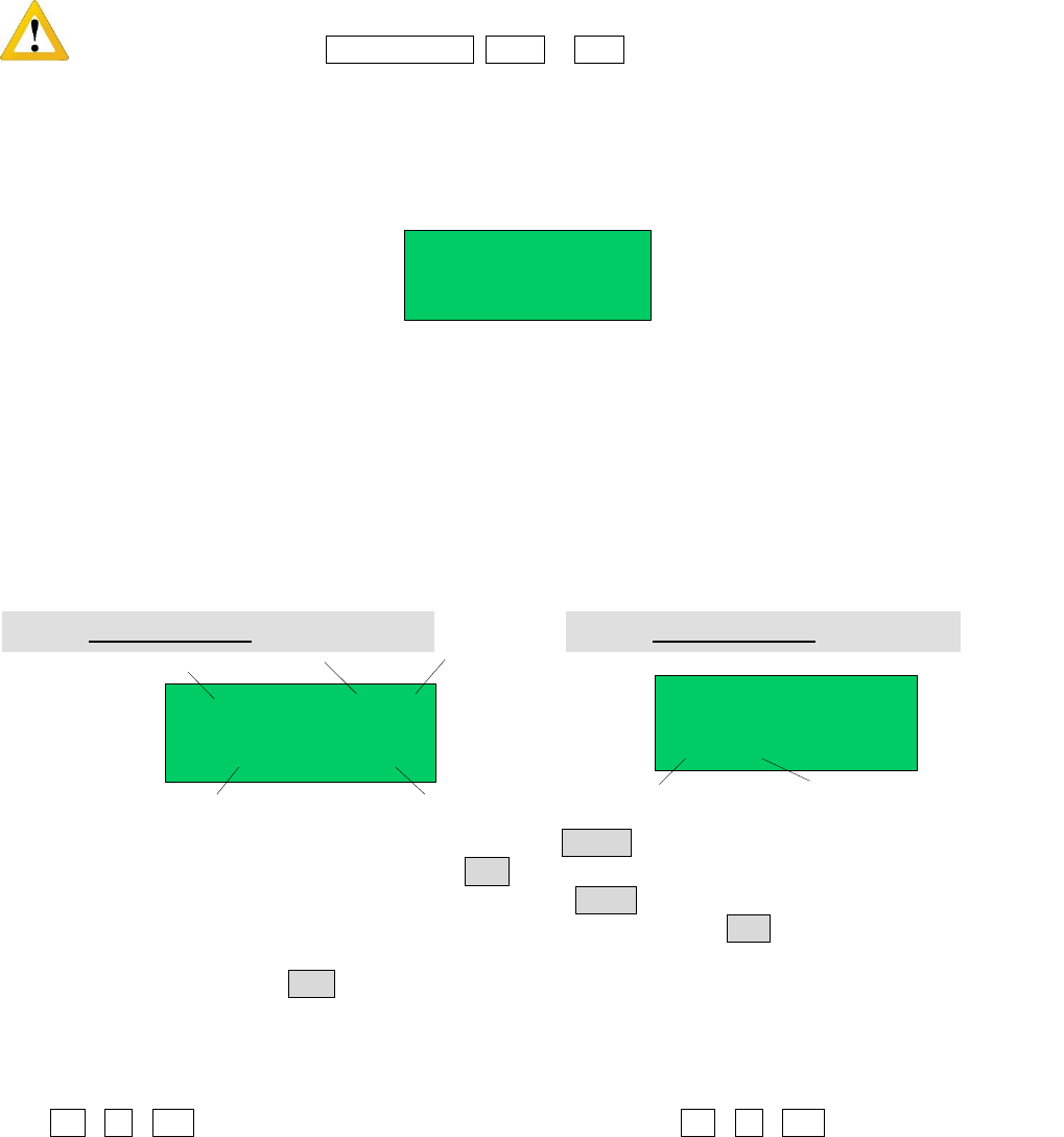
All information showing on the LCD display are as follows:
SJ001
N:0003
01/30
STOP
File Name
Processing State
File No. File Count
Processing Times
SJ001
0001/0002
01/30
STOP
Set Times about
the Loop-Work
Current
Processing Times
3. Enter the “Origin calibration Interface” by pressing the “HOME” button.
4. Enter the “Testing Interface” by pressing the “ESC” button.
5. Enter the “Loop-work Processing Work” by pressing the “LOOP” button.
6. In any sub-menu, return to the “File Processing Interface” by pressing the “ESC” button, but the set parameters
will not be saved.
7. In any submenu, press the “ENT” button to save the set parameters and then return to the “Processing Interface”.
4.2.1 Select Processing File
1. Select the processing file with the six directional buttons.
2. “ \ \ Z ” buttons can be used to select previous file, and “ \ \ Z ” buttons can be used to
select the next file.
Fig. 4-2: Processing Interface of non Loop-work
Fig. 4-3: Processing Interface of Loop-work
Fig. 4-1: Initialization Interface