00195376-05_SM_D1_D1i_D2_D2i_EN.pdf - 第164页
Service Work Pick&Place Head 4.5.2 Replacing the Vacuum Control System, F ilte r and Additional Volume 164 Service Manual SIPLACE D1/D1i/D2/D2i Installation ► Installation is performed by fo llowing the above instruc…
Service Work
4.5.2 Replacing the Vacuum Control System, Filter and Additional Volume Pick&Place Head
Service Manual SIPLACE D1/D1i/D2/D2i 163
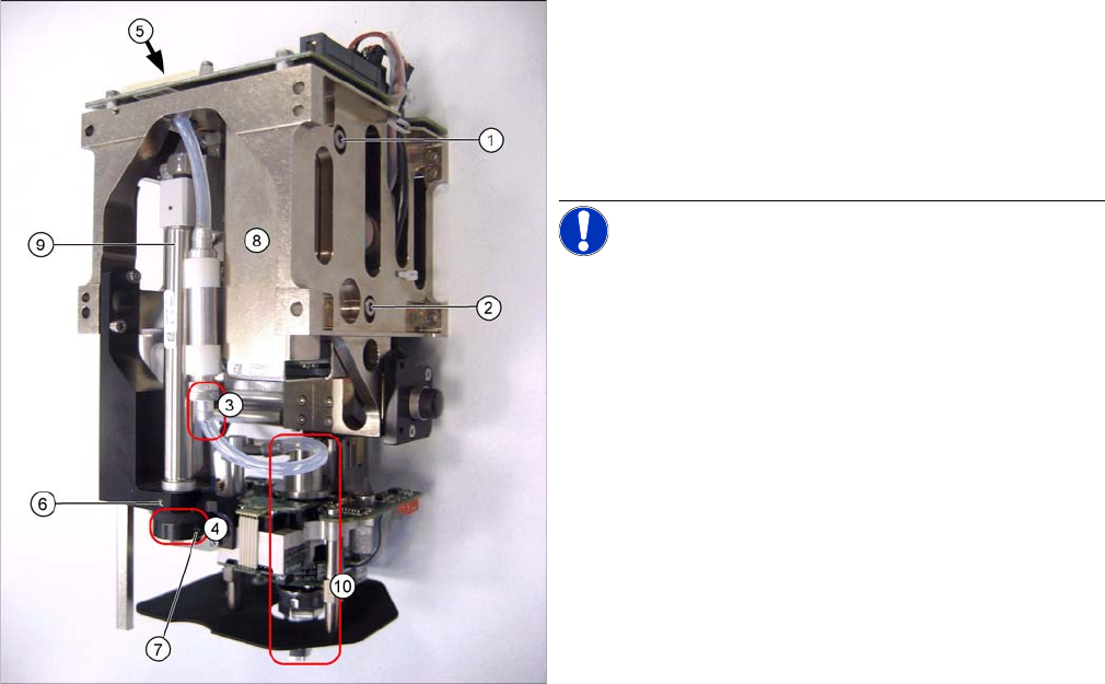
TWIN segment 1 front view / TWIN segment 2 rear view
► Open the threaded pin (7) in the stopper (4) of the re-
turn unit.
► Pull the return unit downwards at the stopper, hold
the hexagonal shaft and unscrew the stopper.
► Open the threaded pin (6) on the return unit and turn
the return unit to the side.
NOTICE! This is only required for the analog
vacuum generator. The controller and filter can be re-
moved from the digital vacuum control system without
this step.
► Disconnect the silicone hosefrom the bottom connec-
tion (3) of the additional volume.
► Unscrew the vacuum control system (8) by loosening
the fastening screws at (1) and (2).
► Pull the vacuum control system downwards so that it
can be unplugged from the head main board (5).
► Unthread the vacuum control system next to the re-
turn cylinder (9) and above the DP turning unit (10) on
the Z mechanics.
Service Work
Pick&Place Head 4.5.2 Replacing the Vacuum Control System, Filter and Additional Volume
164 Service Manual SIPLACE D1/D1i/D2/D2i
Installation
► Installation is performed by following the above instructions in the reverse order.
► Perform a complete installation check. (see "4.5.2.3 Installation Check" [ ➙ 166])
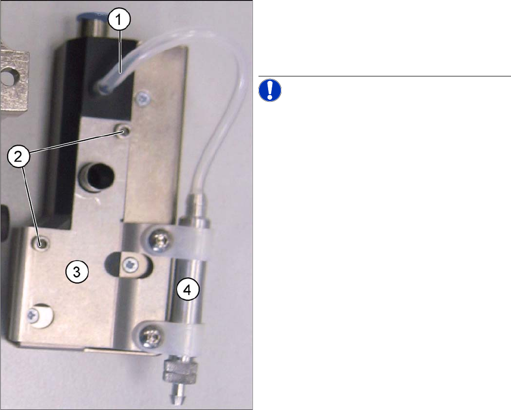
► Disconnect the silicone hose (1) from the vacuum
control system.
► Loosen the two fastening screws (2) and remove the
holder (3) for the additional volume (4) from the vac-
uum control system.
NOTICE! These two drillings (2) mean that the
holder ONLY fits on the analog vacuum control valve.
Service Work
4.5.2 Replacing the Vacuum Control System, Filter and Additional Volume Pick&Place Head
Service Manual SIPLACE D1/D1i/D2/D2i 165
4.5.2.2
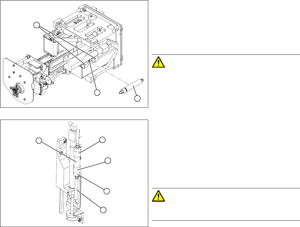
4.5.2.2 Replacing the Additional Volume (Filter) for the Analog Vacuum Control System [03013061-xx]
Replacing the Additional Volume (Filter) for the Analog Vacuum Control System [03013061-xx]
Removal/Installation
► Remove the vacuum hoses on the vacuum control
system and on the rotary axis.
► Loosen the two clips (2) for the additional volume with
air filter (1).
► Loosen the screw fastening the clamping piece (3) for
the clips.
CAUTION! This air filter unit may NOT be used
in combination with the digital vacuum generator. The
volume has been exactly designed for the respective
controller type.
► Fit the additional volume with the air filter (1) facing
downwards, with the clips (2).
► Connect the vacuum hose. Turn the filter so that the
vacuum hose (4) runs in a loop towards the rotary ax-
is.
► Fasten the filter so that the bottom union nut (3) is fit-
ted closely to the clip (2). When moving upwards, the
Z axis must not hit any part of the Twin head .
CAUTION! Kinked vacuum hoses must be re-
placed.
Make sure the vacuum hose is never kinked or jammed.
► Push the Z axis upwards. The rotary axis and the vac-
uum hose must not touch the base.
► Perform a complete installation check. (see "4.5.2.3
Installation Check" [ ➙ 166])
1
3
2
2
4
1
3
2