00195376-05_SM_D1_D1i_D2_D2i_EN.pdf - 第172页
Service Work Pick&Place Head 4.5.5 Replacing the Ma in Head Board [00352833-xx] 172 Service Manual SIPLACE D1/D1i/D2/D2i Legend 1. Head main bo ard (fitted on the top of the TWIN seg - ment) 2. Fastening screws with …
Service Work
4.5.5 Replacing the Main Head Board [00352833-xx] Pick&Place Head
Service Manual SIPLACE D1/D1i/D2/D2i 171
Removal/Installation
4.5.5
4.5.5 Replacing the Main Head Board [00352833-xx]
Replacing the Main Head Board [00352833-xx]
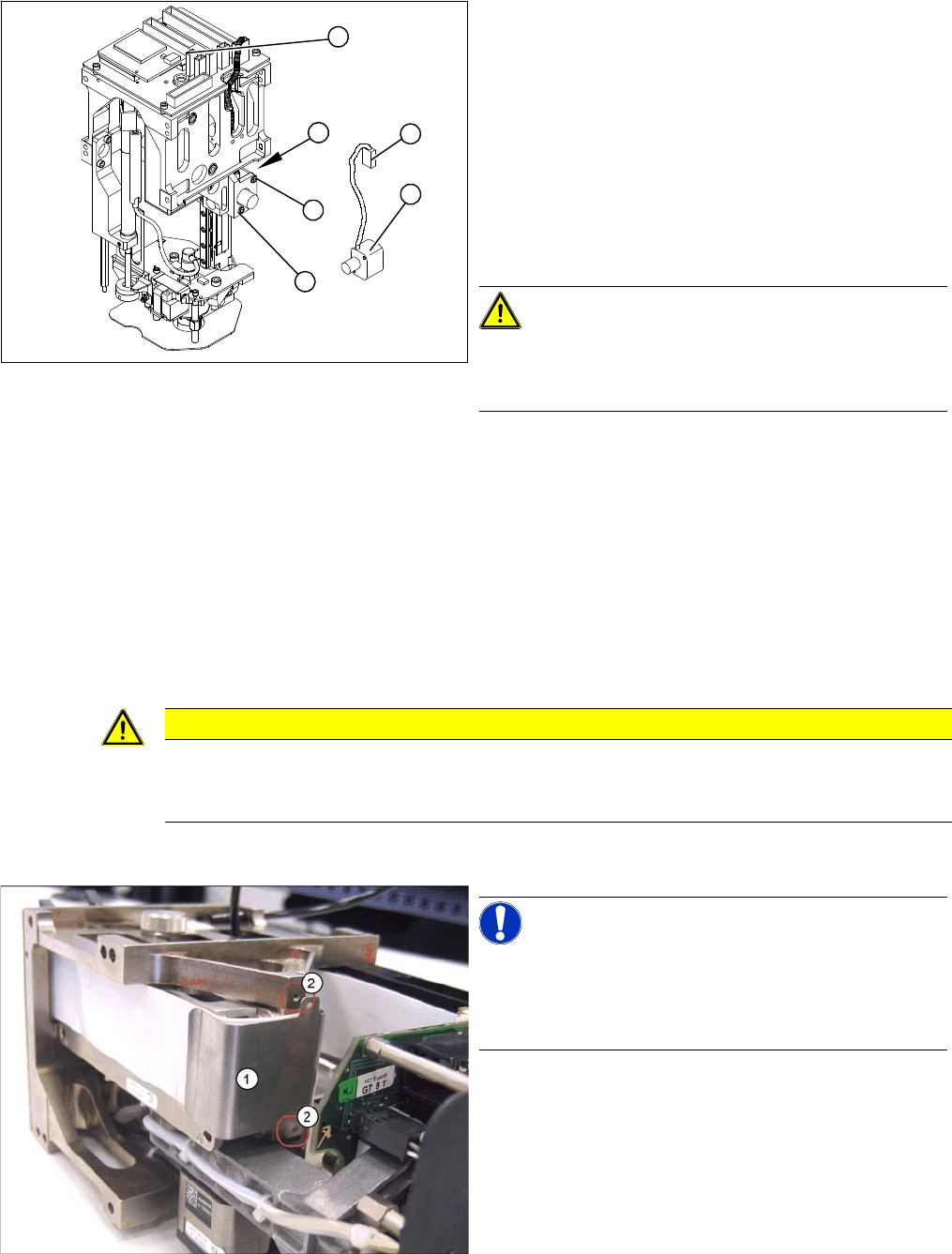
Removal
► Remove the P&P head from the machine.
► Loosen the two screws (4) fastening the mount at the
side.
► Remove the cable ties and unplug the press-fit con-
nection (3).
► Unthread the cable as far as the head board (5).
► Loosen the screws (2) fastening the incremental en-
coder (1).
► Unplug the press-fit connection (3) and extract the in-
cremental encoder (2).
CAUTION! Do not damage the incremental
scale!
The Z axis scale is situated under the incremental encod-
er.
► Fit the new incremental encoder so that there is a gap
of 0.4 mm between it and the scale. Use the corre-
sponding thickness gauge (plastic).
► Make sure that the mount and the incremental encod-
er are installed parallel to one another. Where neces-
sary, correct the play at the holes (within the
tolerance) and tighten the screws.
► Check the track signals.
4
2
5
1
3
2
CAUTION
Digital pressure control valve
The digital pressure control valve needs to be fitted with version [00352833-09] of the head
main board.
NOTICE! Connectors
A number of connectors are unplugged during replace-
ment work. Always mark their original positions so that
these can be easily allocated again when service work is
finished.
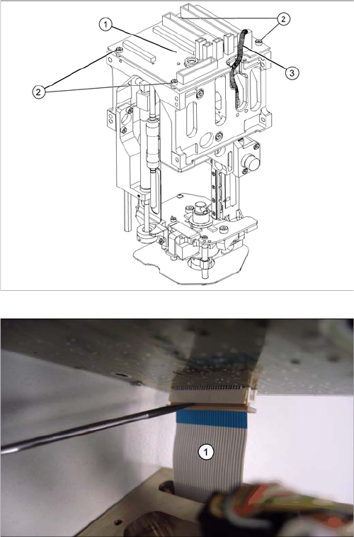
► Dismantle the relevant segment of the TwinHead.
► Loosen the two screws (2) fastening the flat ribbon
cable clamp (1).
Service Work
Pick&Place Head 4.5.5 Replacing the Main Head Board [00352833-xx]
172 Service Manual SIPLACE D1/D1i/D2/D2i
Legend
1. Head main board (fitted on the top of the TWIN seg-
ment)
2. Fastening screws with spacer sleeves under the
board
3. Connectors (2 on gantry, 2 to segment)
► Unplug all connectors (3) from the head main board
(1) (2 connectors from the TWIN segment, return cyl-
inder, Z axis incremental encoder).
► Loosen the four fastening screws (2). Watch out for
the four spacer sleeves under the board. These can
be grasped and removed with a small Allen key.
► Carefully pull the main head board (1) up and off. This
also disconnects the supply plug on the vacuum gen-
erator.
► Completely open the connector fixtures on the foil flat
ribbon cableand remove the foil flat ribbon cable(1).
Service Work
4.5.6 Replacing the Control Cable for the DP Unit - Force Sensor [03005289] Pick&Place Head
Service Manual SIPLACE D1/D1i/D2/D2i 173
Installation
4.5.6
4.5.6 Replacing the Control Cable for the DP Unit - Force Sensor [03005289]
Replacing the Control Cable for the DP Unit - Force Sensor [03005289]
Overview
► Connect the foil flat ribbon cable completely into the
connector (contacts must be fully covered) and fix the
connector strain relief.
► Carefully connect the new head main board (1). This
also reconnects the vacuum generator.
► Fit the fastening screws (2) with the spacer sleeves.
► Reestablish all connections to the electricity supply
(3).
► Fit the Twin segment again.
CAUTION
Transfer the machine data to the EPROM!
Transfer the machine data from the station to the intermediate distributor.
► Follow the instructions in "6.6.13 Transmitting the Head-Specific Data (from SW601)"
[ ➙ 260].
Legend
1. Control cable for DP unit/force sensor
2. Flat ribbon mount
3. Main head board
4. Force measuring board
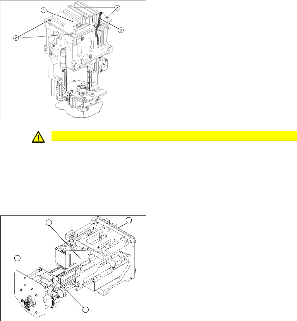
► Remove the P&P head from the machine.
1
4
3
2