00195376-05_SM_D1_D1i_D2_D2i_EN.pdf - 第170页
Service Work Pick&Place Head 4.5.4 Z-axis Incremental Encoder (Read Head) on the P&P Head [03000102-xx] 170 Service Manual SIPLACE D1/D1i/D2/D2i 4.5.4 4 . 5 . 4 Z - a x is I n c r e m e n t a l E n c o d e r ( R …
Service Work
4.5.3 Replacing the Z axis Return Unit [03001361] Pick&Place Head
Service Manual SIPLACE D1/D1i/D2/D2i 169
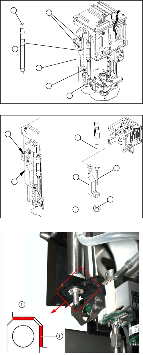
Removal/Installation
► Loosen the grub screw on the bumper (1) and un-
screw the bumper.
► Loosen the grub screw (5) on the mount (3).
► Loosen the two screws (2) holding the mount (3).
► Disconnect the plug (6) from the coupling.
► Disconnect the hose to the head adapter.
► Remove the return unit (4).
► Insert the return unit(1) through the opening in the
mount (2).
► Reconnect the hose and plug.
► Screw the mount (2) back on.
► Make sure that the mount edge (5) is parallel to the
Twin Head casing (4) (may not protrude beyond it).
Make sure you have the correct distance (0.6 mm) to
the movable part of the head (see following diagram).
► Screw the bumper (3) back in. The piston rod (6)
must be flat against the bumper in extended state.
► Fasten the bumper position with the grub screw (7).
Legend
1. Correct distance of mount to the movable part of the
head: 0.6 mm (production specification)
5
6
1
4
3
2
7
6
1
5
4
3
2
Service Work
Pick&Place Head 4.5.4 Z-axis Incremental Encoder (Read Head) on the P&P Head [03000102-xx]
170 Service Manual SIPLACE D1/D1i/D2/D2i
4.5.4
4.5.4 Z-axis Incremental Encoder (Read Head) on the P&P Head [03000102-xx]
Z-axis Incremental Encoder (Read Head) on the P&P Head [03000102-xx]
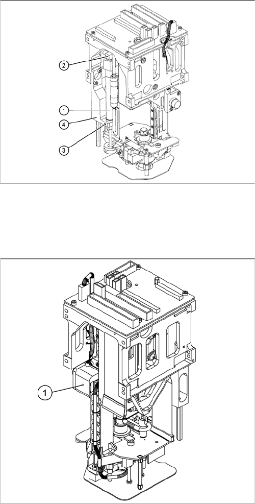
Overview
► Turn the return unit (1) in the mount so that the cables
and plugs (2) do not touch the casing. This prevents
the cables being damaged during movement.
► Fix the return unit (1) with the grub screw (3) to the
mount (4).
Legend
1. Z-axis incremental encoder (read head)
Service Work
4.5.5 Replacing the Main Head Board [00352833-xx] Pick&Place Head
Service Manual SIPLACE D1/D1i/D2/D2i 171
Removal/Installation
4.5.5
4.5.5 Replacing the Main Head Board [00352833-xx]
Replacing the Main Head Board [00352833-xx]
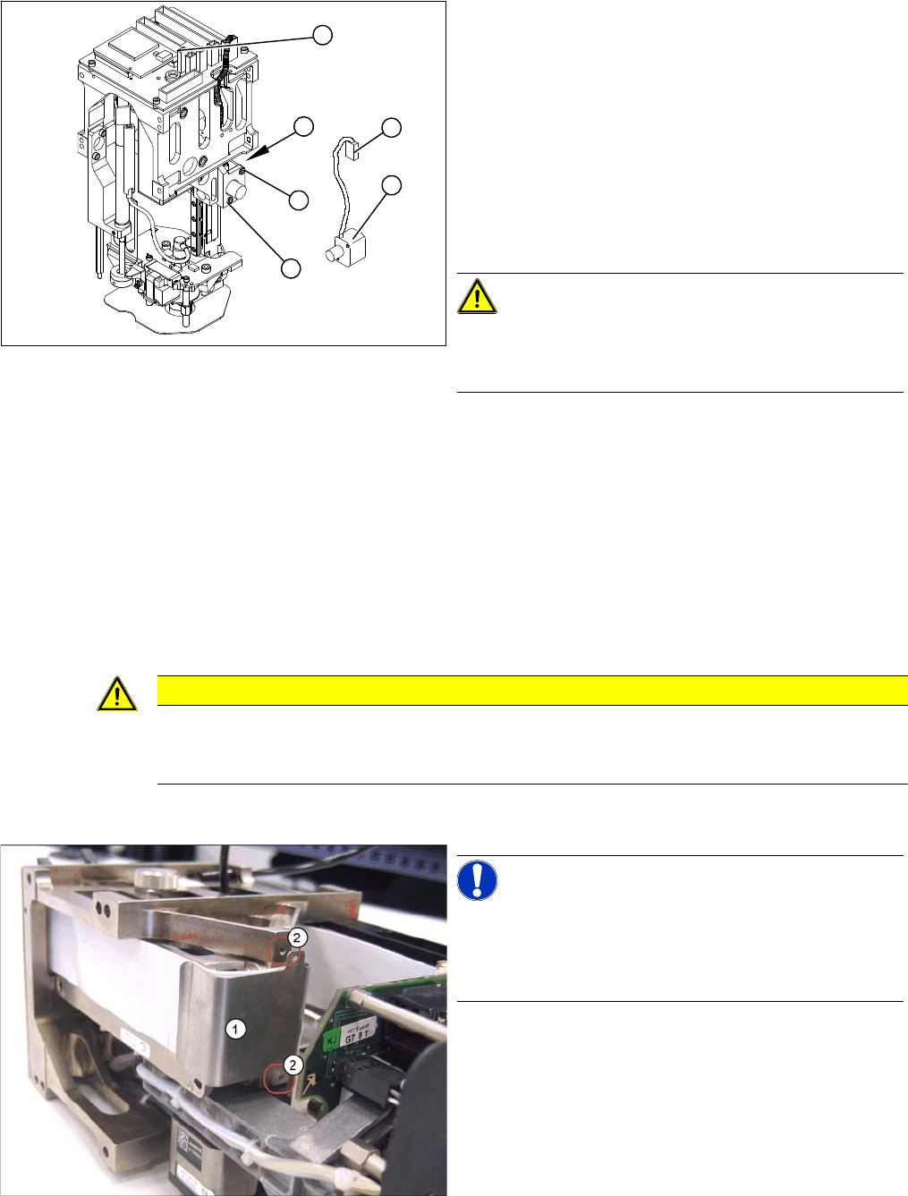
Removal
► Remove the P&P head from the machine.
► Loosen the two screws (4) fastening the mount at the
side.
► Remove the cable ties and unplug the press-fit con-
nection (3).
► Unthread the cable as far as the head board (5).
► Loosen the screws (2) fastening the incremental en-
coder (1).
► Unplug the press-fit connection (3) and extract the in-
cremental encoder (2).
CAUTION! Do not damage the incremental
scale!
The Z axis scale is situated under the incremental encod-
er.
► Fit the new incremental encoder so that there is a gap
of 0.4 mm between it and the scale. Use the corre-
sponding thickness gauge (plastic).
► Make sure that the mount and the incremental encod-
er are installed parallel to one another. Where neces-
sary, correct the play at the holes (within the
tolerance) and tighten the screws.
► Check the track signals.
4
2
5
1
3
2
CAUTION
Digital pressure control valve
The digital pressure control valve needs to be fitted with version [00352833-09] of the head
main board.
NOTICE! Connectors
A number of connectors are unplugged during replace-
ment work. Always mark their original positions so that
these can be easily allocated again when service work is
finished.
► Dismantle the relevant segment of the TwinHead.
► Loosen the two screws (2) fastening the flat ribbon
cable clamp (1).