00195376-05_SM_D1_D1i_D2_D2i_EN.pdf - 第168页
Service Work Pick&Place Head 4.5.3 Replacing the Z axis Retu rn Unit [03001361] 168 Service Manual SIPLACE D1/D1i/D2/D2i Installation ► Installation is performed by fo llowing the above instructions i n the reverse o…
Service Work
4.5.2 Replacing the Vacuum Control System, Filter and Additional Volume Pick&Place Head
Service Manual SIPLACE D1/D1i/D2/D2i 167
4.5.2.4
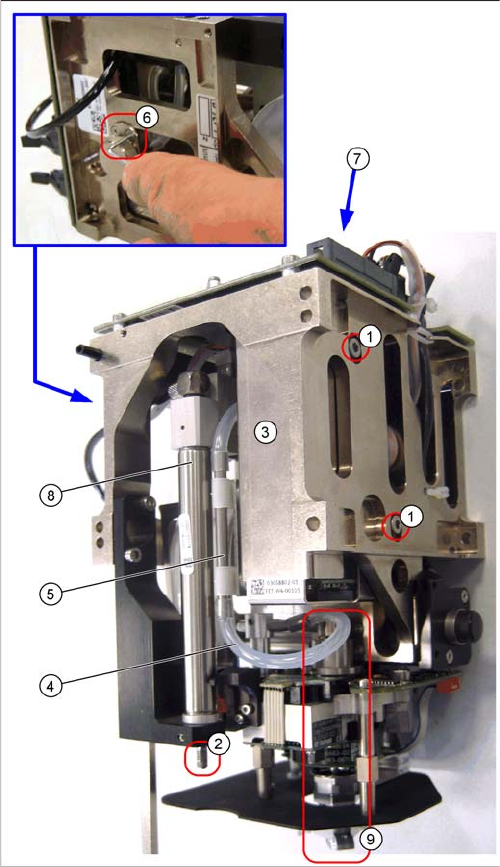
4.5.2.4 Replacing the Vacuum Control System (Version 02 - Digital) [03058802-xx]
Replacing the Vacuum Control System (Version 02 - Digital) [03058802-xx]
Removal
TWIN segment 1 front view / TWIN segment 2 rear view
The digital vacuum generator has a thin high-precision
tube (additional volume tube) in the vacuum supply to the
nozzle. Between this pipe and the vacuum connection of
the vacuum generator, there is an air filter attached to the
TWIN segment.
► Open the threaded pin on the stopper ((2) already re-
moved in the diagram here) of the return unit and un-
screw the stopper.
► Pull the silicon hose (4) off the connecting piece of
the high-precision tube (5).
► Loosen the two clamping screws (6) on the air filter.
► Loosen the two fastening screws (1) on the vacuum
control system (3) and remove the vacuum control
system.
► Pull the vacuum control system downwards so that it
can be unplugged from the head main board (7).
► Unthread the vacuum control system next to the re-
turn cylinder (8) and above the DP turning unit (9) on
the Z mechanics.
Service Work
Pick&Place Head 4.5.3 Replacing the Z axis Return Unit [03001361]
168 Service Manual SIPLACE D1/D1i/D2/D2i
Installation
► Installation is performed by following the above instructions in the reverse order.
4.5.3
4.5.3 Replacing the Z axis Return Unit [03001361]
Replacing the Z axis Return Unit [03001361]
Overview
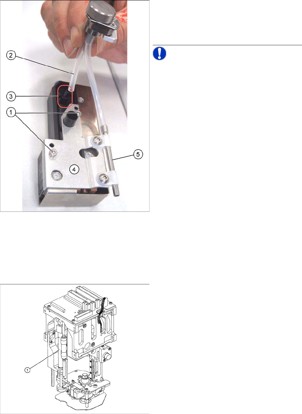
► Pull the silicon hose (2) off the vacuum connection (3)
of the vacuum control system.
► Loosen and remove the two fastening screws (1) for
the high-precision tube holder (5) from the vacuum
control system.
NOTICE! This holder for the digital vacuum con-
trol system has 4 fixture holes, of which the two lower
ones (1) are used.
Legend
1. Return unit
► Remove the relevant P+P module from the machine.
Service Work
4.5.3 Replacing the Z axis Return Unit [03001361] Pick&Place Head
Service Manual SIPLACE D1/D1i/D2/D2i 169
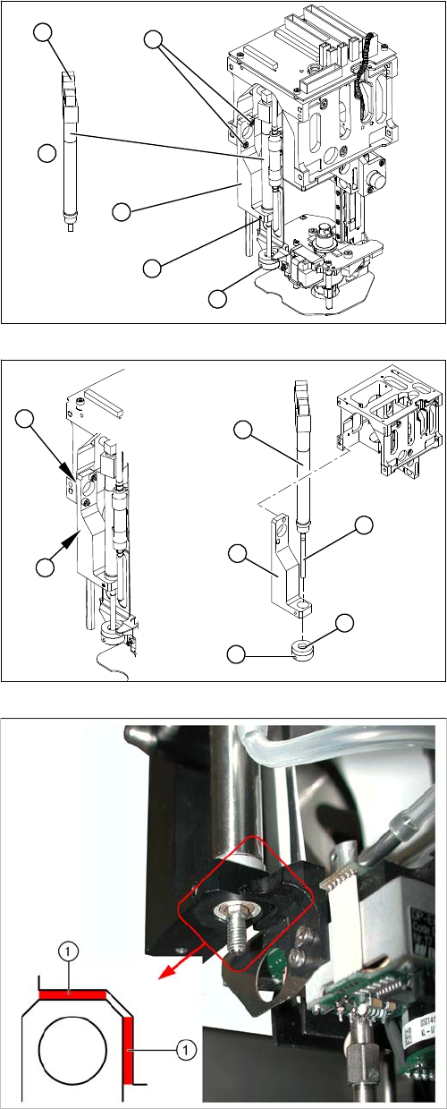
Removal/Installation
► Loosen the grub screw on the bumper (1) and un-
screw the bumper.
► Loosen the grub screw (5) on the mount (3).
► Loosen the two screws (2) holding the mount (3).
► Disconnect the plug (6) from the coupling.
► Disconnect the hose to the head adapter.
► Remove the return unit (4).
► Insert the return unit(1) through the opening in the
mount (2).
► Reconnect the hose and plug.
► Screw the mount (2) back on.
► Make sure that the mount edge (5) is parallel to the
Twin Head casing (4) (may not protrude beyond it).
Make sure you have the correct distance (0.6 mm) to
the movable part of the head (see following diagram).
► Screw the bumper (3) back in. The piston rod (6)
must be flat against the bumper in extended state.
► Fasten the bumper position with the grub screw (7).
Legend
1. Correct distance of mount to the movable part of the
head: 0.6 mm (production specification)
5
6
1
4
3
2
7
6
1
5
4
3
2