00195376-05_SM_D1_D1i_D2_D2i_EN.pdf - 第173页
Service Work 4.5.6 Replacing the Control Cable fo r the DP Unit - Force Sen so r [03005289] Pick&Place Head Service Manual SIPLACE D1/D1i/D2/D2i 173 Installation 4.5.6 4 . 5 . 6 R e p la c in g t h e C o n t r o l C …
Service Work
Pick&Place Head 4.5.5 Replacing the Main Head Board [00352833-xx]
172 Service Manual SIPLACE D1/D1i/D2/D2i
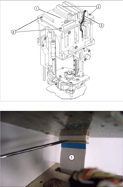
Legend
1. Head main board (fitted on the top of the TWIN seg-
ment)
2. Fastening screws with spacer sleeves under the
board
3. Connectors (2 on gantry, 2 to segment)
► Unplug all connectors (3) from the head main board
(1) (2 connectors from the TWIN segment, return cyl-
inder, Z axis incremental encoder).
► Loosen the four fastening screws (2). Watch out for
the four spacer sleeves under the board. These can
be grasped and removed with a small Allen key.
► Carefully pull the main head board (1) up and off. This
also disconnects the supply plug on the vacuum gen-
erator.
► Completely open the connector fixtures on the foil flat
ribbon cableand remove the foil flat ribbon cable(1).
Service Work
4.5.6 Replacing the Control Cable for the DP Unit - Force Sensor [03005289] Pick&Place Head
Service Manual SIPLACE D1/D1i/D2/D2i 173
Installation
4.5.6
4.5.6 Replacing the Control Cable for the DP Unit - Force Sensor [03005289]
Replacing the Control Cable for the DP Unit - Force Sensor [03005289]
Overview
► Connect the foil flat ribbon cable completely into the
connector (contacts must be fully covered) and fix the
connector strain relief.
► Carefully connect the new head main board (1). This
also reconnects the vacuum generator.
► Fit the fastening screws (2) with the spacer sleeves.
► Reestablish all connections to the electricity supply
(3).
► Fit the Twin segment again.
CAUTION
Transfer the machine data to the EPROM!
Transfer the machine data from the station to the intermediate distributor.
► Follow the instructions in "6.6.13 Transmitting the Head-Specific Data (from SW601)"
[ ➙ 260].
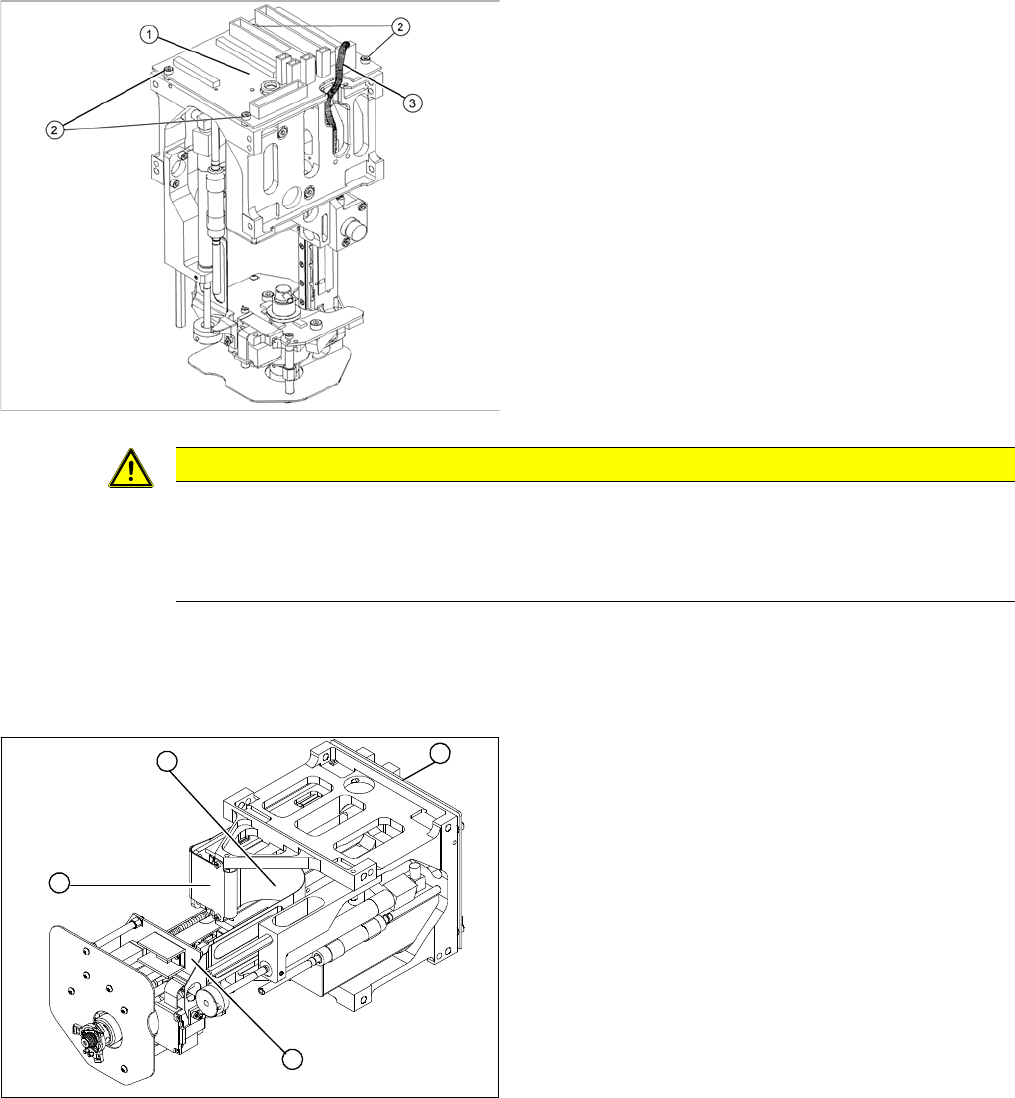
Legend
1. Control cable for DP unit/force sensor
2. Flat ribbon mount
3. Main head board
4. Force measuring board
► Remove the P&P head from the machine.
1
4
3
2
Service Work
Pick&Place Head 4.5.6 Replacing the Control Cable for the DP Unit - Force Sensor [03005289]
174 Service Manual SIPLACE D1/D1i/D2/D2i
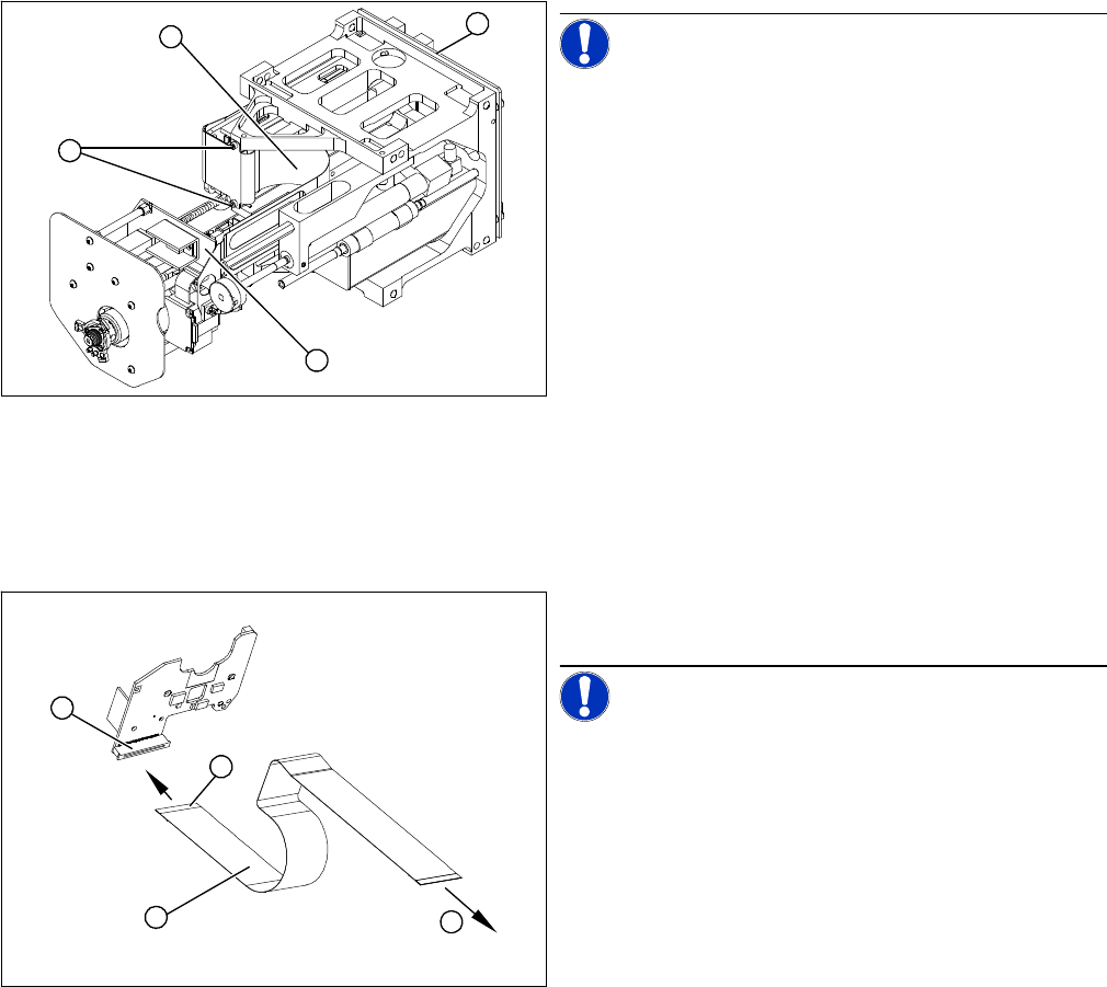
Removal/Installation
NOTICE! Make sure you note the correct con-
tact position of the control cables during removal and in-
stallation. The installation position is marked in blue.
► Disconnect the control cable from the force measur-
ing board (1). To do this, pull the two locking handles
on the plug up and out.
► Loosen the two screws fastening the flat ribbon
mount (2).
⇨ To access the plug, the main head board (3) must
be removed.
► Remove the head main board (3). Take care not to
lose the four spacer sleeves.
► Disconnect the control cable (4) from the main head
board (3) and remove the control cable (4).
► Connect the new control cable to the main head
board (3) and fit the flat ribbon mount (2). Pull the
locking handle upwards.
► Insert the control cable (1) until the contacts (4) fully
engage.
NOTICE! Observe the original installation posi-
tion of the control cable.
► Push the two locking handles down. The control ca-
ble should now sit firmly on the plug (2) of the force
measurement board.
⇨ (3) To the main head board.
1
4
3
2
1
4
3
2