00195376-05_SM_D1_D1i_D2_D2i_EN.pdf - 第215页
Settings 6.3.2 Checking the Track Signals Track Sig nals and Zero Pulse Service Manual SIPLACE D1/D1i/D2/D2i 215 X11 on Y-axis gantry int erface X24 on X-Axis Gant ry Head Distributor 6.3.2 6 . 3 . 2 C h e c k in g t h e…
Settings
Track Signals and Zero Pulse 6.3.1 Checking the Zero Pulse Signal
214 Service Manual SIPLACE D1/D1i/D2/D2i
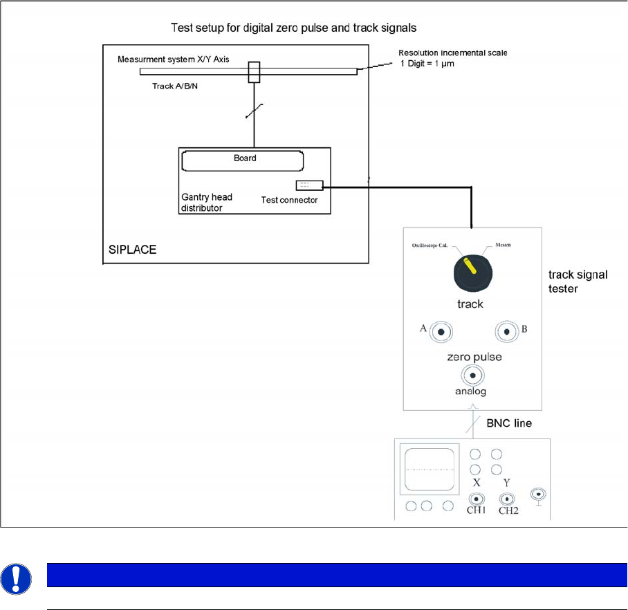
Measurement procedure for checking the digital zero pulse signal and the digital track signals.
NOTICE
The digital track signals can be measured at the test connector with measuring terminals!
Settings
6.3.2 Checking the Track Signals Track Signals and Zero Pulse
Service Manual SIPLACE D1/D1i/D2/D2i 215
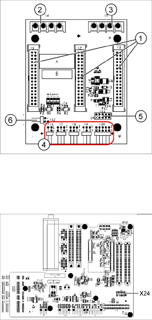
X11 on Y-axis gantry interface
X24 on X-Axis Gantry Head Distributor
6.3.2
6.3.2 Checking the Track Signals
Checking the Track Signals
6.3.2.1
6.3.2.1 Analog Track Signals
Analog Track Signals
► To check the track signals, connect the track signal tester and the oscilloscope. (See "6.3.1.1 Meas-
uring the Analog Zero Pulse Signal" [ ➙ 212].)
Oscilloscope settings: Connect CH1 to track A, CH2 to track B.
► Switch the machine on.
► Switch the track signal tester to Calibrate oscilloscope.
► Set both oscilloscope channels to GND. Place the lines for CH1 and CH2 over one another (on the
zero line of the coordinate system).
► Set both channels to DC, Refr., Non Store, Autotrigger (20 ms).
Legend
1. X1/X2/X3 flat ribbon cable
2. X4 motor Y-axis (U,V,W)
3. X5 motor X-axis (U,V,W)
4. X6 Temperature sensor X motor
X7 End position proximity switch Y axis (not used)
X8 Reference proximity switch Y axis (not used)
X9 Anticrash sensor (not used)
X10 connector for Y axis track signals
5. X11 test connector for Y-axis track signals
6. X12 Y-motor temperature sensor
Connector assignment X11
▪ Pin 1 Ground
▪ Pin 2 Track A
▪ Pin 3 Track A\ A\ mean inverted A
▪ Pin 4 Ground
▪ Pin 5 Track B
▪ Pin 6 Track B\
▪ Pin 7 +5V
▪ Pin 8 Track N
▪ Pin 9 Track N\
▪ Pin 10 Key
Connector assignment X24
▪ Pin 1 Ground
▪ Pin 2 Track A
▪ Pin 3 Track A\
▪ Pin 4 Ground
▪ Pin 5 Track B
▪ Pin 6 Track B\
▪ Pin 7 +5V
▪ Pin 8 Track N
▪ Pin 9 Track N\
▪ Pin 10 Key
Settings
Track Signals and Zero Pulse 6.3.2 Checking the Track Signals
216 Service Manual SIPLACE D1/D1i/D2/D2i
► Voltages V/Division decrease up to 0.5 V/Div.
► Set the track signal tester switch to "Measure".
► Switch the oscilloscope to X/Y --> Illuminated point will appear!
► Move the point into the middle of the display.
► Manually move the selected axis back and forth.
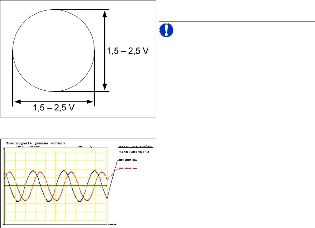
Analog track signals A and B in X/Y oscilloscope mode
► The adjacent picture should appear on the oscillo-
scope.
NOTICE! A new version of the incremental en-
coder (one field lens) can recognize signals from 1.8 to
3.6 Vss.
Analog track signals 90° phase shift
► Switch the oscilloscope from X/Y deflection to normal
mode.
► The adjacent picture should appear on the oscillo-
scope.