00195376-05_SM_D1_D1i_D2_D2i_EN.pdf - 第220页
Settings Axis Control 6.4.2 Checking the X Axis Dynamics 220 Service Manual SIPLACE D1/D1i/D2/D2i 6.4.2.3 6 . 4 . 2 . 3 C o m p a r is o n o f X - A x is T r a v e l P r o f ile f o r C & P 6 / 1 2 a n d P & P H …
Settings
6.4.2 Checking the X Axis Dynamics Axis Control
Service Manual SIPLACE D1/D1i/D2/D2i 219
6.4.2.1
6.4.2.1 Switches and Switch Settings
Switches and Switch Settings
6.4.2.2
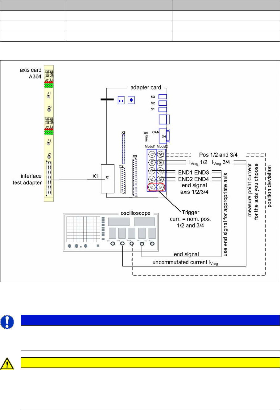
6.4.2.2 Measurement Setup with Adapter Board for A364
Measurement Setup with Adapter Board for A364
Measurement setup with axis test box
▪ Additional connection at channel 4 could be the actual position = target position signal from trigger
m1/2 of the adapter board or the position deviation.
Switches Top switch position Bottom switch position
S3 none none
S2 Signals from axis controller 3 (A3) Signals from axis controller 4 (A4)
S1 Signals from axis controller 1 (A1) Signals from axis controller 2 (A2)
NOTICE
Measure the signals directly on the adapter board!
The position deviation emitted there offers the advantage of showing the actual axis controller
function.
CAUTION
When checking the dynamics, it may be sufficient if you check the travel times and overshoot
behavior of the axis with the SIPLACE axis tester (SAT) display and the values in the settings
tables.
However, when checking for errors, you will need to use a suitable oscilloscope for the dynam-
ics analysis.
Settings
Axis Control 6.4.2 Checking the X Axis Dynamics
220 Service Manual SIPLACE D1/D1i/D2/D2i
6.4.2.3
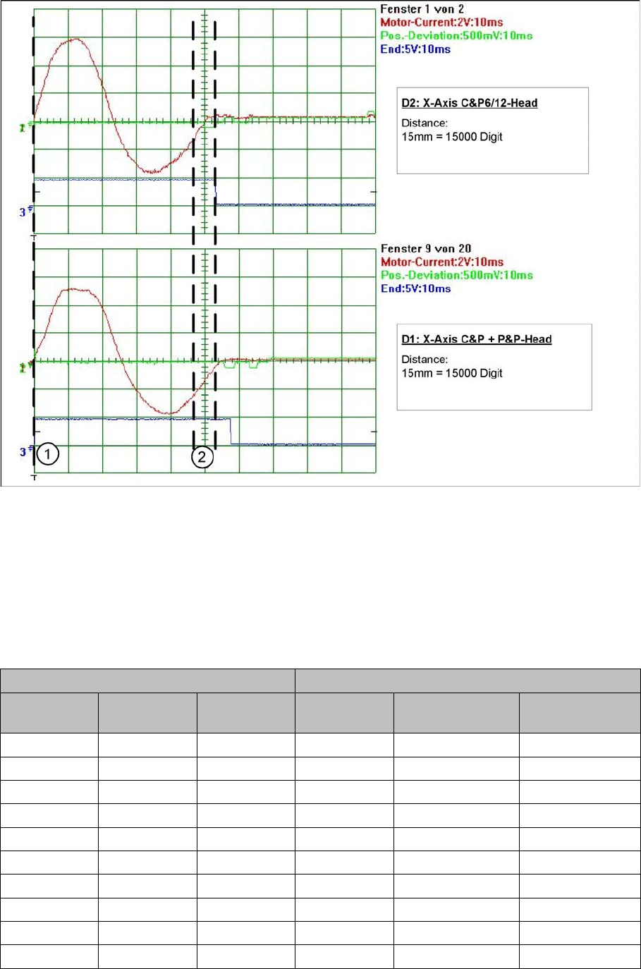
6.4.2.3 Comparison of X-Axis Travel Profile for C&P6/12 and P&P Heads
Comparison of X-Axis Travel Profile for C&P6/12 and P&P Heads
Signal path at 15000 digit travel range of X axis for different head configurations
Legend
1. Axis start
2. The end position signal is triggered at different times, depending on the axis records for both head
configurations.
6.4.2.4
6.4.2.4 X Axis Travel Time Table, According to Placement Heads
X Axis Travel Time Table, According to Placement Heads
Travel times for X gantry axis
D2 machine: C&P6 or C&P12 D1 machine: C&P6 or C&P12 + P&P
Distance / dig-
it
Target time /
ms
Tolerance /ms Distance / dig-
it
Target time / ms Tolerance /ms
500 33 +/-5 500 30 +/-5
1000 35 +/-5 1000 33 +/-5
2000 37 +/-5 2000 39 +/-5
5000 43 +/-5 5000 48 +/-5
15000 56 +/-5 15000 60 +/-5
20000 64 +/-10 20000 66 +/-10
50000 88 +/-10 50000 95 +/-10
100000 117 +/-10 100000 126 +/-10
200000 159 +/-15 200000 174 +/-15
300000 199 +/-15 300000 214 +/-15
Settings
6.4.3 Checking the Y Axis Dynamics Axis Control
Service Manual SIPLACE D1/D1i/D2/D2i 221
6.4.3
6.4.3 Checking the Y Axis Dynamics
Checking the Y Axis Dynamics
6.4.3.1
6.4.3.1 Measurement Setup
Measurement Setup
6.4.3.2
6.4.3.2 Y-axis Travel Profiles for C&P12 Head
Y-axis Travel Profiles for C&P12 Head
6.4.3.3
6.4.3.3 Y Axis Travel Time Table (D1/D2/D1i/D2i)
Y Axis Travel Time Table (D1/D2/D1i/D2i)
NOTICE
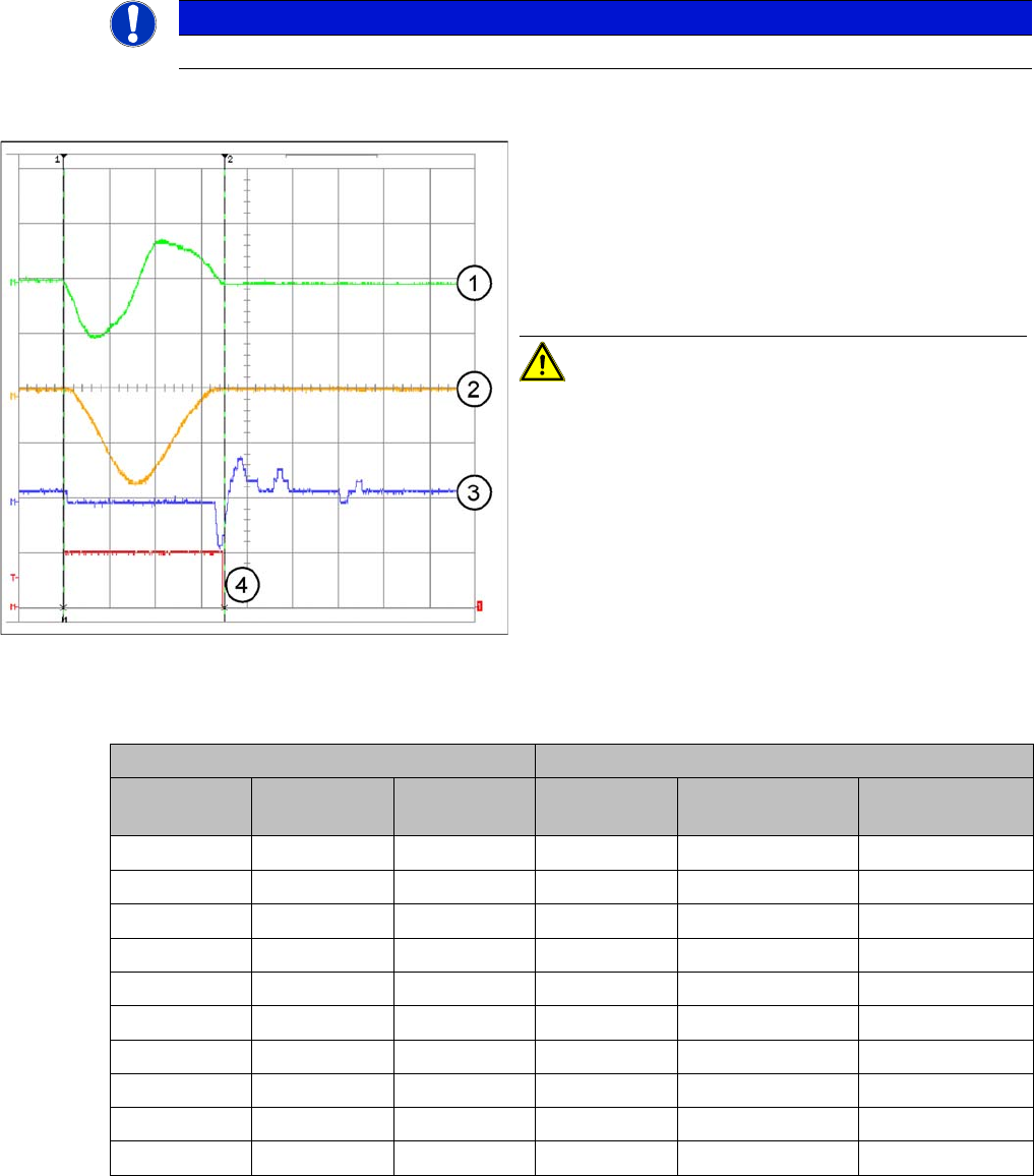
The measurement procedure follows the same preparations and procedures as for the X axis.
Example of y-axis signal path for 15000 digit path
Legend
1. Current signal
2. Speed – signal Vreg (Vnominal)
3. Deviation of position
4. End signal
Distance: 15mm = 15000 Digit
CAUTION! The permissible position deviation
for placement with a C&P12 head: 10 µm (digits)
D2/D2i: C&P6 or C&P12 D1/D1i: C&P6 or C&P12 and P&P
Distance / dig-
it
Target time /
ms
Tolerance /ms Distance / dig-
it
Target time / ms Tolerance /ms
500 45 +/-5 500 45 +/-5
1000 50 +/-5 1000 50 +/-5
2000 59 +/-5 2000 62 +/-5
5000 66 +/-5 5000 75 +/-5
15000 79 +/-10 15000 91 +/-10
20000 90 +/-10 20000 105 +/-10
50000 118 +/-10 50000 133 +/-10
100000 150 +/-10 100000 172 +/-10
200000 196 +/-15 200000 228 +/-15
600000 378 +/-15 600000 425 +/-15